O2iTC23/O2i605CM/O2i607CM/O2i562/O2i675/O2i695 Intensifier IP® Full HD 1080 Specialty IP Camera
User ’s Guide Directions Be careful not to cause any physical damage by dropping or throwing the camera. Especially keep the device out of reach from children. Do not disassemble the camera. No after service is assumed when disassembled. Use only power adapters compatible with the unit. Be careful to prevent moisture or water penetration into the unit. Particular attention is needed when installing the unit.
User ’s Guide Revision History Date Revision th 1.0 May 4 , 2016 Details First manual revision creation. Rev.1.
User ’s Guide Contents 1. 2. Introduction .................................................................................................................................................... 5 1.1. Overview ............................................................................................................................................... 5 1.2. Specifications .....................................................................................................................................
User ’s Guide 1. Introduction 1.1. Overview This product is a multi-codec (H.264, MJPEG) IP camera (or network camera) built with embedded software and hardware technology. It enables real time transmission of synchronized video up to 1,080P and audio data. Remote clients can connect to IP Camera for the real time video/audio data through various client solutions running on PC or smart device. Real time 2-way communication is available through bidirectional audio communication feature.
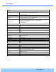
User ’s Guide 1.2. Specifications Camera Image sensor Progressive scan 1/3 inch CMOS 2M pixels Full resolution 1,920 x 1,080 pixels (Full HD) Sync System Internal Lens 2.9mm fixed (3.6mm for O2i562) Day & Night AUTO, DAY, NIGHT Sensitivity Intensifier Max – 0.0005 Lux Back Light Compensation ON / OFF White Balance ATW(2.
User ’s Guide Network Network Protocol - IPv4, TCP, UDP, IGMP, ICMP, ARP, RARP, PPPoE, RTCP - RTP, RTSP, SDP, HTTP, SMTP, FTP, DHCP, UPnP - NTP, DNS, DynDNS Dynamic IP Speco DDNS (free of charge) Security - User ID & Password protection, IP address filtering - Digest Authentication, User Access Log Streaming method - RTSP streaming with proprietary format for control information - standard RTSP streaming - HTTP streaming External Terminals LAN 10/100BaseT LAN (auto MDIX) Alarm input / output Al
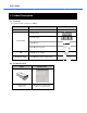
User ’s Guide 2. Product Description 2.1. Contents The product package contains the following : Contents Camera Description Main unit and camera unit Screws (1 type) Anchors (1 type) Accessories L-type type wrench Cable bracket and Screw CD Reference Guide Software & User’s Guide Quick installation guide guide, Guide pattern 2.2.
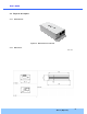
User ’s Guide 2.3. Physical description 2.3.1. External View Figure 2-1. External view of main unit 2.3.2. Dimensions Unit : mm Figure 2-2. Dimensions Rev.1.
User ’s Guide 2.3.3. Front and Rear view of Main Unit Cable bracket screw hole Pin Description 1 Line Output 2 Ground 3 MIC/Line Line Input 4 Relay Output 5 Relay Output Figure 2-3. Front view 6 Sensor Input (-) 7 Connect Camera Sensor Input (+) Connect Camera Unit Figure 2-4. Rear view 2.3.4. Factory Default Switch Factory default switch is provided for returning the IP camera to factory default state. There are two functions assigned to factory default switch. 1.
User ’s Guide 2.4. Functional Description Power : Power input for supplying 12V DC power. Caution : If camera is powered by PoE, do not plug in DC Jack with active DC power into DC power connector. Network (LAN) 100Mbps Ethernet connector (RJ-45) 45) with PoE standard (802.3af). LED on the Ethernet connector shows the status of the camera as follows: s: - Link LED It will be lit with orange color when network cabling is all right.
User ’s Guide Sensor Input Connect external alarm sensor. Examples of sensing devices are infrared sensor, motion sensor, heat/smoke sensor, magnetic sensor, etc. Connect the two wires of the sensors to “Sensor Input”. The sensor type (NC/NO) can be set in admin page. Multiple sensor devices can be connected in parallel. NO/NC Type Photo Coupler Open Collector Type Sensor1+ Sensor Device Sensor Device Sensor1- +12V GND Sensor Power Supply Sensor Power Supply Figure 2-6.
User ’s Guide 3. On Site Installation Use cables and conduits that are suitable for the installation. Particular attention should be paid in the installation so that no moisture is allowed to penetrate into the unit through the cables or conduits during the life time of the product. Products of which the internal parts are exposed to moisture because of improper installation are not covered by warranty. The main unit must not be exposed to weather elements. 1.
User ’s Guide 4. Getting Started 4.1. PC Requirements Audio/Video streaming data received from the camera can be displayed or stored in a PC running client programs.
User ’s Guide 4.2. Quick Installation Guide 4.2.1. Connect PC and camera to network. 1. Prepare a PC to run programs for the installation and video connection (PC is needed to assign IP address to camera) 2. In the case of using PoE, connect the PC and camera to the network using one of the following ways. If your LAN Switch does not support standard PoE, connect the main unit as shown in dotted line in Figure.. The DC power is applied through DC adapter.
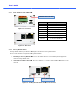
User ’s Guide 3 1 2 9 10 5 4 7 6 8 Click on the field in (3) for sorting and rearranging the list. Select network mode that best suits from the drop down list in (5).. You can choose either Static or ADSL and Auto (DHCP), respectively. If ADSL and Auto are selected, the fields in (6) are deactivated. In case of ADSL, fill the User Name and Password in (8) with the values provided by your ISP. If DDNS service is needed, Check at the box and fill the empty field with hostname hostnam you want in (7).
User ’s Guide [e.g.] Port 8080 Note : Active-X X module should be installed on your PC before actual connection. If your PC is not connected to the internet, you cannot download Active-X Active X module. Most convenient way of installing the Active-X X module is installing Speco-NVR which is available from m the CD or our web site. Connection to Admin Page Basic Control Figure 4-3. Web Viewer Default ID and password of Admin Page are “admin”, “1234”.
User ’s Guide 4.2.4. Additional settings through connection to the Admin Page All parameters of the camera are factory default out of the box. For a more sophisticated target application, parameters need to be changed through the admin page. The admin page can be connected through “http://IP_Address:Port_Number/admin.htm” ID and password of the administrator are required. Default ID and password are “admin”, “1234”.
User ’s Guide 5. Troubleshooting 5.1. No power is applied In case of Standard PoE (Power over Ethernet) Power supply through standard PoE is possible only when the following conditions are met. 1. Standard PoE is supported on the product. 2. The LAN switch supports standard PoE. Make sure that both the IP camera and the LAN switch support standard PoE (IEEE 802.3af) In case of DC adapter If PoE is not applied, the power and network connection should be made through separate cables.
User ’s Guide 5.2. Cannot connect to the Video Check the status of the network connection through PING test. Try the following on your PC : - Start > Run > Cmd > Ping IP address (Ex : Ping 172.16.42.51) - If “Reply from ~” message is returned ( ① in the figure below), the network connection is in normal state. Try connection to the video again. If the problem persists, or refer to other trouble shooting notes. - If “Request timed out” message is returned.
User ’s Guide 5.3. Technical Assistance If you need any technical assistance, please contact technical support.. For immediate service please provide the following information. 1. Model name 2. MAC address and Registration number 3. Purchase date 4. Description of the problem 5.
User ’s Guide Appendix A – Important Notice in Exchanging SD Card (Micro SD) SD Card is a non-volatile memory device for storing video and audio data on the product. Note that continuous recording to the SD Card will cause the memory cell to wear out, eventually resulting in failure. When you plug out the SD Card for replacement or other purpose, follow the steps below in order to prevent data loss or crash of the SD Card. 1. Press factory default button for 1 sec to unmount the SD Card .