
Manual

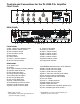

21) AC fuse holder.
22) Zone 1~7 output terminals. In addition to the normal 70V and 25V line outputs, there
are seven groups of 70V or 25V, line terminals for 7 zones which can be selected using the
push buttons on the front panel.
23) MOH output level control. Controls volume of MOH output. (Music on hold)
24) MOH output terminals. Provided two MOH outputs 600 Ohm, 1 Volt and 8 Ohm, 1 Watt.
25) TEL / PAGING balanced input terminals. Accepts a balanced telephone paging signal.
26) TEL / PAGING input level control. Controls audio level of telephone input.
Note: MOH output features an internal selector jumper (factory set on AUX-1) AUX-1~3 when
background music is provided at the AUX inputs. MOH output function depends on the jumper
location or locations that are selected, see illustration on page 8.
Screw terminal designations: G-GND, HOT-Signal positive, COM-Signal negative/common.
Overcoming Ground Loop Problems
If the amplifier is mounted in a rack unit (Use rack mount part # PBM-RK2), or is used with
equipment having its own ground, it is necessary to ensure that ground loops and the
associated problems of hum on the output signal are not introduced by the ground wiring. (see
warning)
Warning
To overcome this problem if it occurs, the electrical and the mechanical ground on the amplifier
may be separated by completely removing the wire connecting the power source to ground.
CONSULT AN ELECTRONICS TECHNICIAN TO ACCOMPLISH THIS TO AVOID POTENTIAL
PERSONAL INJURY OR A HAZARDOUS CONDITION.
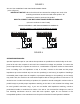
SPEAKER CONNECTION
The rear panel of the amplifier contains a 7 screw terminal strip for connection of speakers.
BE CAREFUL TO CONNECT SPEAKERS PROPERLY, see impedance and line voltage instructions
below.
The speaker lines are to be connected directly between the appropriate COM terminal on the 7
screw terminal strip and the terminal corresponding to the impedance of the speaker(s) or of the line
voltage selected. (70V or 25V)
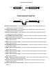
4, 8 and 16 OHM CONNECTIONS (refer to figure 3).
Connect the cables to the terminals on the 7 screw terminal strip provided. Use the screw terminals
which correspond to the impedance of the speaker(s). One lead must always be connected to the
COM. This is just an example. If in doubt consult a qualified technician.
(+)
(+)
(+)
(+)
TWO 8 SPEAKERS
(IN PARALLEL)
Ω
TWO 4 SPEAKERS
(IN SERIES)
Ω