User Guide (Ver. 1.1) Model: D4VT, D8VT, D16VT 4, 8, 16 Channel HD TVI Digital Video Recorder About the User’s Guide Before operating the unit, please read this user’s guide thoroughly and retain it for future reference.
Cautions Explanation of Graphic Symbols This symbol indicates the presence of important operating and maintenance (servicing) instructions in the literature accompanying the product. This symbol indicates the presence of “dangerous voltage” within the product’s enclosure that may be of sufficient magnitude to constitute a risk of electric shock, property damage, personal injury, or death. WARNING To reduce a risk of fire or electric shock, do not expose this product to rain or moisture.
These Precautions must be Followed for Safety Reasons Warning Do not use if the unit emits smoke. Do not disassemble the unit. Do not place any heavy or sharp objects on the unit. Do not place on uneven surface. Do not expose to shock or vibration. Do not move the unit when the unit is powered on. Do not block, and allow dust to accumulate in the air vents. Do not restrict airflow of the unit; doing so can damage the unit.
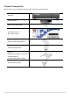
Product Components Please make sure the following components are included as specified below. DVR Unit Remote Control Battery1.
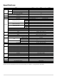
Specifications Input Video Output Audio Alarm Serial ITEM Description Number of Channels Camera Main Monitor Sub Monitor(option) Input / Output (HDMI support) Audio Codec Sensor Input Alarm Output RS-485 Compression 1920x1080 Camera Input 1280x720 Camera Input Recording Analog Camera Input Playback Backup Storage User I/F Network Features Network Access Power Temperature Humidity Weight Dimension 1920x1080 1920x540 1280x720 640x360 1280x720 640x360 960H D1 CIF Recording Quality Grade Recording M
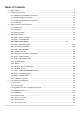
Table of Contents 1. Main Features ............................................................................................................................... 9 2. Initial Boot up Process ................................................................................................................. 10 2-1. Initial Boot up and Basic Time Setup ..................................................................................... 10 2-2. Setting Daylight Saving Time ...................................
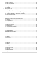
5-3-6. Go To Last Time ................................................................................................................. 56 5-3-7. Go To Specific Time ........................................................................................................... 56 5-3-8. Archive List ........................................................................................................................ 56 5-3-9. Log List ..........................................................................
7-8-1. Addition, Delete, and Modify of DVR Sites ......................................................................... 86 7-8-2. Connect and Disconnect .................................................................................................... 88 7-8-3. Still-image Capture During Live .......................................................................................... 89 7-8-4. Recording Video on Local PC During Live ........................................................................
1. Main Features Easy Record, Copy and Setup Easy Search by Thumbnail Preview Easy Copy Digital Deterrent function H.
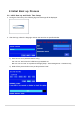
2. Initial Boot up Process 2-1. Initial Boot up and Basic Time Setup 1. During the first boot up, the following logo and message will be displayed. 2. After the logo, select the language and set date and time as specified below. 1) User have to set a password before using. Can not use ‘1111’ when the initial boot up password set. But user can set ‘1111’ as a password through [Setup - User Management – Password set] 2) DVR will not proceed when user put the password ‘1111’.
(EZ Setup Page Reference, Page 15-16) 2-2. Setting Daylight Saving Time To enable Daylight Saving feature/NTP synchronization, take the following steps. 1. Enter the SETUP mode. The default Username is “ADMIN” and Password is “1111”. 2. Go to SETUP > SYSTEM > DATE & TIME SETUP 3. Select ON from the DAYLIGHT SAVING dropdown menu.
2-3. Setting NTP (Network Time Protocol) 1. SETUP > SYSTEM > NTP SETUP > ON 2. Select the proper TIME ZONE time.
Table 2.3.1.
NV Nevada GMT-8 GMT-7 NH New Hampshire GMT-5 GMT-4 NJ New Jersey GMT-5 GMT-4 NM New Mexico GMT-7 GMT-6 NY New York GMT-5 GMT-4 NC North Carolina GMT-5 GMT-4 ND North Dakota GMT-6 GMT-5 ND North Dakota (W) GMT-7 GMT-6 OH Ohio GMT-5 GMT-4 OK Oklahoma GMT-6 GMT-5 OR Oregon GMT-8 GMT-7 OR Oregon (E) GMT-7 GMT-6 PA Pennsylvania GMT-5 GMT-4 RI Rhode Island GMT-5 GMT-4 SC South Carolina GMT-5 GMT-4 SD South Dakota (E) GMT-6 GMT-5 SD South Dakota (W)
2-4. EZ SETUP VT Easy installation(Right-Click on the Main Screen and click ADVANCE MENU) Figure 2.4. EZ Setup Screen 2.4.1. Setup DATE & TIME, Recording configurations. 1 2 3 4 5 Figure 2.4.1. EZ Record Setup Procedure ① Select EZ Record for Date/Time and Recording Setup, Click NEXT to proceed.
② Description of EZ Record Setup is displayed, Click NEXT to proceed. ③ Set up the Date/Time settings and click NEXT to get to the recording setup. ④ Select the recording mode and click NEXT to get to the recording setup. ⑤ Select one of options and click NEXT to finish the setup. 2.4.2. EZ NETWORK (Using an internet connection) 1 2 3 Figure 2.4.2. EZ NETWORK Setup Procedure ① DVR automatically checking the network and configuration by scanning in few seconds.
3. Name, Function and Connection 3-1. Front Panel DxxVT Figure 3.1.1. Front panel Table 3.1.1. Front LED and Port of DxxVT Name POWER HDD USB Port Description LED light is on when power is applied to the system. LED light is on when the system is recording video data. This USB port for archiving footage into a USB device. (USB 2.0 connector) 3-2. Connectors D4VT D8VT D16VT Figure 3.2.1.
① VIDEO IN: Video input port. ② VIDEO OUT: Switchable (Composite Video Output or Spot Monitor) ③ VGA: VGA (Video Graphics Array) output port. Connects to the PC VGA monitor. ④ HD VIDEO OUT: HDMI output port. Connections to the HDMI monitor (1920x1080). ⑤ AUDIO IN: D4VT/ D8VT: Four connectors for audio input. D16VT: use the included audio splitter cable ⑥ AUDIO OUT: D4VT/ D8VT: One connector for audio output. D16VT: use the included audio splitter cable.
3-3. Remote Control ① ID: To set the remote control ID. ② REC: To start and stop manual recording ③ SEARCH: To go to SEARCH menu. ④ F/ADV: During playback – To move the playback position 60 seconds forward . During Pause – To move the playback position moves 1 frame forward ⑤ F/REW: During playback – To move the playback position 60 seconds back. During Pause – To move the playback postion 1 frame back. ⑥ FF: To fast forward the recording.
4. Setting up the DVR The following sections detail the initial setup of the DVR. Menu screen will close if user input is not received in 5 minutes. 4-1. Setup – Main Live Screen To enter the setup menu, right click on the mouse and select setup from the submenu or press the setup button on the remote control. Figure 4.1.1. Live Screen and Quick Operation Window When the DVR prompts the LOG-IN window, enter the PASSWORD using the virtual keyboard, or the remote control.
Figure 4.2.1. SYSTEM Setup Screen Table 4.2.1. Menu Items in SYSTEM Setup Screen Item DESCRIPTION Description Press the button to view the system information. (Software Version, Storage Size, IP Address, MAC Address and DDNS Status) LANGUAGE Select the display language using the mouse or the remote control. Once a language is selected, the display language will change. DATE DISPLAY FORMAT Select the date display format using the mouse or the remote control.
Select DAYLIGHT SAVING using the mouse or the remote control and select the appropriate daylight saving time zone. The options are: OFF: Daylight saving is turned off. USA: Applies the USA daylight saving time. EU: Applies the EU daylight saving time. - Select the GMT AREA using the mouse or the remote control. - Set the time difference with the standard time. OTHERS: If the time zone is neither USA nor EU, set the date and time of the daylight saving period.
DVR sends E-MAIL Notification when the NTP server time is faster than the system time with bellow message. “NTP server time is faster than the system time. In this case, NTP server time is ignored to protect the user data. User must set the time manually. SYSTEM TIME: Mon Oct 10 13:46:49 2011 SERVER TIME: Mon Oct 10 13:33:12 2011 DVR ID: DVR IP ADDRESS: 172.16.2.46” SEND EMAIL SERVER TYPE: MANUAL, GMAIL, HOTMAIL, AOL or YAHOOMAIL MAIL PORT: Assign Mail Port number.
SYSTEM EVENT NOTIFICATION HEALTH CHECK – OFF, ON (Allows the user to set MAIL STATUS periodically) : DAILY or WEELY or MONTHLY VIDEO CLIP SETUP: Setup the duration of video clip for PRE RECORD and POST RECORD. EVENT AND NOTIFICATION – OFF, ON (Allows the user to set EVENT NOFICIATION ON or OFF) HEALTH CHECK / RESTART / SHUTDOWN / PANIC RECORD - Enable Email Notification in the event a problem occurs with the VT. ALARM-IN – Enable Email Notification when the camera detects sensor.
HDD FAILURE – Enable Email, Beep and Alarm output Notification when the HDD fails. 4-2-1. How to use ‘Cloud’ - Notice : User have to have a ‘Google Drive’ Account - Save video clip on the Google Drive and playback though Mobile device. 1) How to set (Setup – System – System Event Notification – Cloud) 1-1) Click icon 1-2) Enter Google Drive Account 1-3) Video clip will be save at Google Drive when ‘Alarm-In’ and ‘Motion’ triggered.
4-3. Setup – RECORD Mode In the SETUP menu, select the RECORD tab. Then, the RECORD menu is displayed as pictured below. Navigate through the menu items or change the settings using the mouse or the remote control. Figure 4.3.1. RECORD Setup Screen Table 4.3.1. Menu Items in RECORD Setup Screen Menu Item SITE Description Select a channel for applying the following settings using the mouse or the remote control. To change the values of all channels, take the following steps.
SENSOR Select the sensor setting for the selected channel. RECORDING PRE RECORD Enable/disable pre-event recording. Pre-event recording time is up to 20 minutes. POST EVENT Set the post event recording time duration for the specified channel. RECORD (10~60 seconds) AUDIO Enable/disable audio recording for the specified channel. SCHEDULE Set the recording schedule.
4-3-1. Recording Schedules To setup a recording schedule, select SCHEDULE in the RECORD menu. Navigate through the menu items or change the settings using the mouse or the remote control. Select the CHANNEL, select one of the recording settings: NONE, CONTINUOUS or MOTION, then Highlight the area for the selected setting. To copy a schedule to a different channel, select the channel from the COPY SCHEDULE menu, then click the COPY button. . Figure 4.3.2.
4-4. Setup – DEVICE Mode In the SETUP menu, select the DEVICE tab. Then, the device menu is displayed as pictured below. Navigate through the menu items or change the settings using the mouse or the remote control. Figure 4.4.1. DEVICE Setup Screen Table 4.4.1. Menu Items in DEVICE Setup Screen Item Description ALARM OUT/ Set the sensor, motion, and video loss for triggering alarm relay BEEP DURATION HDD Error and Video Loss can trigger beeping DIGITAL DETERRENT .
(1 – Lowest sensitivity, 9 – Highest sensitivity) KEY TONE Enable/disable key tone. REMOTE CONTROL ID Set the remote control ID. 1. Select ID. 2. Input the remote control ID number. 3. An icon will indicate on the Live Screen if the remote control ID is synchronized. The options are from 0 to 99 Select the type of each sensor. SENSOR Option is Off, Normal Open or Normal Close. 4-4-1. Digital Deterrent Trigger audio message via motion detection or sensor. Figure 4.4.2.
4-4-2. Keyboard Controller & PTZ Setup To control the PTZ functions of the camera, connect the PTZ controller to the RS-485 port on the back of the chassis with CAT5 (or equivalent) cable. ① Connect the RS-485 cables of PTZ camera to the RS-485 port on the rear panel. Figure 4.4.3. Device Mode Setup Screen Figure 4.4.4.
② Open the PTZ sub menu by selecting the submenu button. Figure 4.4.5. PTZ Control Setup Screen Note: Connect PTZ cameras that support RS-485 directly to the RS-485 port. If the camera is controlled through an RS-232C interface, use an RS-232C to RS-485 to RS-232C signal converter.
4-4-3. Spot Out Figure 4.4.7. SPOT-OUT Setup Screen Table 4.4.3. Menu Item in SPOT-OUT Setup Screen Item Description SPOT OUT Only 1 Spot Out is available to use. SPOT TYPE SPOT 1 supports only FULL type. (1 channel only) SPOT ON EVENT Enable/disable channel change if an event occurs on a channel. SPOT EVENT Set the dwell time for the display of the event activated channel. DWELL TIME (3-10 sec) SEQUENCE Enable/disable sequential display of spot channel in full screen.
4-4-4. Motion Zone Setup Select MOTION ZONE using the mouse or the remote control and select either PARTIAL ZONE or FULL ZONE using the mouse control. The default value is FULL ZONE. If FULL ZONE is selected, the motion zone grid screen is not displayed. Only set the level of sensitivity for MOTION SENSITIVITY. FULL ZONE: The motion sensor is active on the whole screen. PARTIAL ZONE: The motion sensor is active in the set detection frame.
4-5. Setup – DISPLAY Mode In the SETUP menu, select the DISPLAY tab. Then, the DISPLAY menu is displayed as pictured below. Navigate through the menu items or change the settings using the mouse or the remote control. To return to the previous setup menu screen, press the ESC button. Figure 4.5.1. DISPLAY Setup Screen Table 4.5.1.
mouse or the remote control. Select a channel to apply the following settings using the mouse. Set the channel name. Press the right square button and set the channel NAME name and select OK. The name can be made up to 36 characters. COVERT Enable/disable display of the specified video channel in live display. COLOR TUNING Control the brightness, contrast, hue and saturation.
DNS (PRIMARY) Enter Primary DNS address that is assigned for the DVR DNS (SECONDARY) Enter Secondary DNS address that is assigned for the DVR DDNS Dynamic Domain Name System (DDNS) allows a DNS name to be constantly synchronized with a dynamic IP address. In other words, it allows using a dynamic IP address to be associated with a static domain name so others can connect to it by the static name. Enable/disable using domain name address through DDNS server.
Figure 4.6.2. NETWORK Setup Screen – DDNS Table 4.6.2. DDNS Item Description ENABLE DDNS Enable/disable the Dynamic Domain Name Service. HOST NAME This item allows the user to setup a domain name manually, using virtual keyboard displays as shown. SUBMIT/UPDATE When manual host name input is done, move the cursor to this item and select ON to submit the settings. ezDDNS Enable/disable ezDDNS to register the host name automatically. 4-6-3.
- D16VT: Up to 240 fps @CIF for 16 channels. Individual Channels can be set with different RESOLUTION, FRAME RATE, and QUALITY. In case of using MOBILE, QUALITY can be setup up to LEVEL2. Figure 4.6.4.
4-7. Setup – USER MANAGEMENT Mode In the SETUP menu, select the USER MANAGEMENT tab. Then, the USER MANAGEMENT menu is displayed as pictured below. Navigate through the menu items or change the settings using the mouse or the remote control. Figure 4.7.1. USER MANAGEMENT Setup Screen Table 4.7.1. Menu Items in USER MANAGEMENT Setup Screen Item Description AUTHORITY Only the Admin will have access to the menu.
ADMIN, USER1, USER2, USER3: Selected Checkbox: The user can access the function. Blank Checkbox: The user can not access the function. USER NAME Change the name of USER1, USER2 and USER3. SETUP Click “ENTER” after naming. PASSWORD Options are ADMIN, USER1, USER2 and USER3. SETUP Select USER PASSWORD using the mouse or the remote control and press SEL button. Select user type and enter the current password. And, enter a new password, enter the same password again to confirm and select OK.
4-8. Setup – STORAGE Mode In the SETUP menu, select the STORAGE tab. Then, the STORAGE menu is displayed as pictured below. Navigate through the menu items or change the settings using the mouse or the remote control. Figure 4.8.1. STORAGE Setup Screen Table 4.8.1. Menu Items in STORAGE Setup Screen Item OVERWRITE Description When enabled, the DVR will continue recording and overwrite the oldest existing recorded data once the hard drive is full.
DISK INFO Hard drive information. Displays the following information: RECORDING Enable recording limit : The amount of data recorded in HDD will be limited LIMIT to the most recent number of days as set by “RECORDING LIMIT DAYS”. Disable recording limit : When OVERWRITE is ON, DVR will continue to record when HDD is full and overwrite older data. When OVERWRITE is OFF, DVR will stop recording when the HDD is full. RECORDING Set the recording limit days.
4-9. Setup - CONFIG Mode In the SETUP menu, select the CONFIG tab. Then, the configuration menu is displayed as pictured below. Navigate through the menu items or change the settings using the mouse or the remote control. Figure 4.9.1. CONFIGURATION Setup Screen Table 4.9.1. CONFIGURATION Setup Item Description EXPORT TO User can save the current configuration (Setting values) of the DVR to the USB USB flash drive.
4-9-1. Firmware Upgrade 1. In the USB flash drive root directory, create a new folder named “upgrade” 2. Create sub-folder for each model under “upgrade” folder and copy each firmware file to their folder. “d4VT” for D4VT: “main_D4VT_speco_*.*.*_201****” “d8VT” for D8VT: “main_D8VT_speco_*.*.*_201****” “d16VT” for D16VT: “main_D16VT_speco_*.*.*_201****” 3. Plug in the USB flash drive. 4. Navigate to CONFIG menu of SETUP. 5. Select SOFTWARE UPGRADE. 6. Follow the procedure from Figure 4.9.
5. Live, Search and Playback 5-1. Live View In the Live screen, video inputs from the cameras are displayed as they are configured in the Display Setup screen. When the mouse is right clicked, and the quick operation window will be displayed as below. Figure 5.1.1. Live Screen and Quick Operation Window On the bottom of the screen, various On-Screen Display (OSD) symbols, which indicate the status of the DVR, are described in Table 5.1.1.
Table 5.1.1. Status Indicator Icons in Live Viewing Screen Icon Description Indicates the DVR is locked. Note) to unlock, right click on the live view screen and select on Unlock. Audio mute. Audio channel output can be selected from the quick operation menu Indicates that alarm is set. Indicates that alarm output is activated. Event indicator. When there is an event (motion recording, video loss, HDD fail, S.M.A.R.T), this icon will be highlighted. Indicates that a network client is connected to the DVR.
SUPER EZ COPY Direct Backup of the selected channel to USB flash drive without going through the search mode. ENABLE MANUAL Manual Record button. Click this button to enable manual recording. RECORD Also known as Panic Record. ADVANCED MENU EZ SETUP Select this option to start EZ Setup Wizard AUDIO Select this option to set an audio channel to output; (Channel 1 through 4, Audio Mute). CAMERA PTZ Select this option and the PTZ user interface will appear.
5-1-1. PTZ Control Table 5.1.3. Menu Items in PTZ Control Window Item Description INITIALIZE PAN/TILT Initialize the PTZ settings of the selected camera Select PAN/TILT using the remote or mouse, then press SEL. Adjust the tilt by using ▲▼(UP/DOWN) buttons ZOOM/FOCUS Adjust the pan by using ◀▶(LEFT/RIGHT) buttons Select ZOOM/FOCUS using the remote or mouse, then press SEL. Adjust the zoom ▲▼(UP/DOWN) buttons Adjust the focus ◀▶(LEFT/RIGHT) buttons OSD Select OSD to enter the menu.
5-2. Digital Zoom in Live and Playback Screen VT series supports Digital Zoom feature during live and playback mode. 1. Double click the target channel. 2. Click the left button of the mouse and drag to make rectangular shape. 5-3. SEARCH Screen To enter the search screen menu, select SEARCH menu on the screen using the mouse or press SEARCH icon on live screen. Figure 5.3.1.
5-3-1. EZSearch The EZSearch window is used to find stored video with ease using the thumb nail playback screen. Figure 5.3.2. Calendar Screen STEP 1. 24 Hourly Thumbnail Screen STEP 3. Every 10 seconds Figure 5.3.3. Channel Selection Screen STEP 2. Every 2 minutes and 30 seconds STEP 4.
Figure 5.3.4. Second Thumbnail Screen When the EZSearch menu is selected, a calendar is displayed that highlights dates with recorded data. 1. Select a specific date on the calendar. 2. Select a channel from Channel Selection Screen. Then the Thumbnail Search screen displays 24 thumbnails, one for each hour of the day. 3. Second step shows every 2 minutes and 30 seconds screen. 4. Third step shows every 10 seconds. 5. Fourth step shows every 1 seconds 6. Playback the selected image. 5-3-2.
1) Select the start time and End time that user want to search 2) Set Zone as ‘Partial’ or ‘Full’ 3) Partial zone can select the area that user want. 4) Click this after selection as ‘Partial’ then user can drag the area. 5) Click right mouse button when the area selection was finished. 6) Select ‘SEARCH’ then show the detected motion lists at the right blank.
7) Click the list that user want to playback. 8) ‘Export’ and ‘E-Mail’ icon will be activate for backup or mail notice 5-3-3. Time Line Search The CALENDAR Search window is used to find the stored video by using the time line bar.
Figure 5.3.7. Calendar Screen Figure 5.3.8. Time-Line Search Screen When the Timeline menu is selected, the user can see a calendar, which displays recorded dates with highlights. Select a specific date and time. Click and drag the red time indicator bar to the desired hour. User can select a specific minutes using a button in the above red box. Press the PLAY button after selecting the specific time. Press the PREV to return to the SEARCH window. 5-3-4.
User can find a data of the specific channel and event using a button in the above red box as following Figure 5.3.9. Press the PREV to return to the SEARCH window. Figure 5.3.10. Event Search Screen 5-3-5. Go To First Time You can access the oldest recorded data on the DVR hard drive by selecting GO TO FIRST TIME on the SEARCH window. Press the PREV to return to the SEARCH window. 5-3-6.
frame of the selected video, then the user can export the selected data. 5-3-9. Log List You can access the LOG list search screen by selecting LOG on the SEARCH window. Figure 5.3.12. Log List Screen When the Log menu is selected, the user can see a calendar, which has a log data. Select a specific date and press NEXT button, and then the log data will be displayed. Press the SAVE button to save the data and then the data is saved as a text file format. 5-4.
Table 5.4.1. Button Functions in PLAY Mode Button Description 1x, 2x, 4x, 8x,16x, 32x speeds for D4VT 1x, 2x, 4x, 8x,16x for D8VT 1x, 2x, 4x, 8x for D16VT Single Channel backward playback speed 1x, 2x, 4x, 8x, 16x, 32x, 64x Jump/Step backward. The playback position moves 60 seconds backward. Press to play or pause recorded video. Jump/Step forward. Playback position moves 60 seconds forward.
6. Export and Back Up 6-1. Still Image Backup onto USB Flash Drive Still images can be captured and archived onto a USB flash drive or an USB external hard drive in live mode or while playing back recorded video. 1. Select a specific channel, which wants to backup on live screen. 2. When you press SNAPSHOT button on Quick operation window, the media selection window screen will display. 3. Once you press START button, the system will capture a still image and archive onto a USB flash drive.
6-2. Video Backup onto USB Flash Drive during playback Video can be captured and archived onto the USB flash drive or a hard drive while playing back the recorded video. In playback mode, press the 1. When you press BACKUP button to launch the backup function. BACKUP button on the selected channel or all channels, the DVR will ask whether to archive a Still Image, a NSF or AVI and select the proper media type. 2. Select USB DRIVE (Flash Drive) to back up less than an hour.
5. The following shows the image to complete the backup. Select lose to return to the previous screen. 6-3. EZCopy: Video Backup onto USB Flash Drive during playback Using EZCopy feature, Video can be easily archived onto the USB flash drive or a hard drive. In playback mode, press the EZCOPY button to launch the backup function. 1. Press EZCOPY button on the selected channel or all channels. 2. Then, EZCOPY START time will display. 3.
4. EZCOPY window will display. The DVR will ask whether to archive a NSF or AVI. 5. After backup format is selected, also select media type and channel(s) to archive the data to the media. 6-4. Transferring Still Images or Video from the ARCHIVE List The stored data in the hard drive can be found in the ARCHIVE list in the SEARCH window. User can back up still images or video into the storage device from the ARCHIVE list. 1.
6-5. Playback of Backup Video 6-5-1. AVI Format AVI format: AVI format video can be played back by Window Media Player™ or other media player that is compatible with AVI format video. 1. Please install the Decoder Filter that the DVR copies “DvrPlayer” folder on USB flash drive with the video. Decoder Filter is exported to the “/DvrPlayer” folder of the USB drive. Decoder Filter 2. Otherwise, the video and time stamp over video can’t be properly played back and wont be displayed on Window Media Player™.
6-5-2. NSF Format NSF format: NSF format video can be played back using the HDplayer that the DVR copies to “DvrPlayer” folder on USB flash drive with video. Use the mouse scroll to use digital zoom in and out feature.
7. Network Access Using the Multi-Sites Network Viewer 7-1. Overview The SpecoTech Multi Client is a multiple site monitoring client software with; video, audio, and alarm signals from the DVRs over the network. The SpecoTech Multi Client does not limit the number of DVR units to register. The program displays up to 16 DVRs and supports dual monitors. On the program, user may control PTZ cameras on the DVRs.
7-3. Installation of the Program 1. Insert the provided CD in the CD drive and double-click “SpecoTech Multi Client (XXXX).exe” 2. Select a destination folder and click “Next”. 3. Select the program folder and click “Next”. 4. The installation status screen is displayed. 5. After the installation is completed, “SpecoTech Multi Client” icon displays on the desktop screen.
7-4. Live Window When installation is completed, double click the “SpecoTech Multi Client” icon on your desktop to start the program. 7-4-1.
7-4-2. Control Buttons Button Description Click this icon to run a playback window to search and play videos that LOCAL PLAYBACK are recorded in the local PC. Click this icon to run a playback window to search and play videos that REMOTE PLAYBACK are recorded in the remote DVR. THUMBNAIL REFRESH: Click this icon to refresh and renew thumbnail image of the connected sites. SITE ADDITION: Click this icon to open ‘Site Addition’ window.
7-5. Search and Playback Window 7-5-1. Main User Interface You can access to search window by clicking the search icon (Local Playback / Remote Playback) on the upper right of the Live Window.
7-5-2. Main Control Panel Button Description Click this icon to run a playback window to search and play videos that LOCAL PLAYBACK are recorded in the local PC. Click this icon to run a playback window to search and play videos that REMOTE PLAYBACK are recorded in the remote DVR. Display the site information and the connection status. CONNECT Click this icon to connect the selected site/sites. DISCONNECT Click this icon to disconnect the selected site/sites.
To change a timeline scale from 24 hours to 60 minutes. The timeline shows recorded data in color on the bar. You can adjust the timeline scale and move it to the time you wish to playback. Then click the play icon to display the recorded video. Playback buttons. EZSEARCH: Thumbnail search over the network. - Shows 24 thumbnail images, one for each hour from 00:00 to 23:00. - Each hour is further broken up 24 segments; each is 150sec.
7-5-3. SMART SEARCH 1) User can search with selected area 2) Click right mouse button when playback 3) ‘Smart Search’ will search in the selected area only. 4) ‘Smart Search’ checking the motion and event from the selected area.
6) Select any of search Thumbnail then selected event will playing.
Setup of SpecoTech Multi Client Click the setup icon to setup the configuration of SpecoTech Multi Client software. The SETUP window is displayed as below. 7-6-1. General Security Option: Set a password for security options. Select security options and set a password. Then when you access any of selected functions, you need to enter the password. You can also set the save path for capturing and backup. Save Path: Specify the location to save captured still image for Capture and Backup data.
7-6-2. Event Event log can be archived and searched. Event Log: Specify the location to save event logs and select event to archive. Event Search: Event log can be searched from the selected time.
7-6-3. Record Record Setup: You can set the recording conditions as the following; Always, Event, or Auto record. And you can also select target DVR/DVRs and channel/channels. When you set the recording condition to event, you can set event for motion or alarm with duration. Record Local Storage Setup: You can select the local disk to record and the amount of disk space you want to allow the program to use for recording.
7-6-4. Display You can select the OSD (On Screen Display) to be displayed. 7-6-5. Language English, French and Spanish is selectable.
7-6-6. About “About” provides network client version information.
7-7. Remote Setup The menu settings for the DVR unit can be set over network. Put the cursor of the mouse on the channel, which is connected to the site and right click on the mouse to open the submenu. Then the following window is displayed as below. Select the REMOTE SETUP. Then the setup window is displayed. The specified menu screen is displayed on the upper left of the screen. Enter the password of the DVR when prompted.
7-7-1. System Select System to set system and time settings. DATE DISPLAY FORMAT: Select the date display format. CLIENT ACCCESS: Enable/Disable remote access through network client software. NTP SETUP: Sets whether to synchronize the time using NTP server or not. o Primary SNTP Server: Input the NTP primary server address. o Secondary SNTP Server: Input the NTP secondary server address. o Time Zone: Select the time zone.
o SEND MAIL TEST: Examine the function with registered information. USER NAME: Name the DVR SYSTEM RESTART SYSTEM EVENT NOTIFICATION Allows the user to set EVENT NOFICIATION ON or OFF o HEALTH CHECK (Allows the user to set MAIL STATUS periodically) : DAILY or WEELY or MONTHLY o HDD TEMPERATURE o HDD BAD SECTOR o HDD ALMOST FULL o VIDEO CLIP SETUP: Setting the duration for pre and post recording.
7-7-2. Record Select RECORD tab to set the recording conditions. These settings apply to the specified channel only. Recording Setup o RESOLUTION: Sets the resolution for the recordings. The value applies to an individual channel. o FRAME RATE: Sets the recording rate. o QUALITY: Sets the image quality in 5 levels. o RECORDING: Sets the recording mode. o RECORDING MODE: CONTINUOUS, SCHEDULE, MOTION, SENSOR o PRE RECORD: Sets whether to perform or not pre recording.
7-7-3. Device Select Device to set Spot Out, Enable/Disable CVBS Out, motion zone. ALARM OUT: Set the alarm out duration. DIGITAL DETERRENT: Set the schedule of digital deterrent function and upload the sound file to DVR. CONTROLLER: Set the controller baud rate and ID. PTZ: Set the PTZ baud rate, protocol, and ID. SPOT: Enable/Disable the SPOT OUT and SEQUENCE. MOTION: Setup the motion detection area and the sensitivity.
7-7-4. Display Select the DISPLAY tab to set the DISPLAY conditions. These settings apply to all channels. OSD: Sets whether to display or not, the date and time as well as channel number on the screen. OSD CONTRAST: Adjust the character contrast on the screen. MAIN MONITOR SEQUENCE: Setting for automatically switching the displayed video. SEQUENCE DWELL TIME: Sets the interval for automatically switching the screens.
7-7-6. User Management Select the USER MANAGEMENT tab to set the DISPLAY conditions. 7-7-7. Storage Select Storage to configure continued recording settings by overwriting the hard disk and the storage period for the recording data. OVERWRITE: Continues recording by writing over previous recordings when HDD is full. DISK INFO: Shows the information of HDD installed in DVR RECORDING LIMIT: Sets whether to limit or not, the recording data storage period. 7-7-8.
7-8. Operation 7-8-1. Addition, Delete, and Modify of DVR Sites 7-8-1-1. Addition of Sites 1. Click SITE ADDITION button. And then the following window will be displayed as below. o Site Name: Input a name that properly describes a site. o IP Address: Input IP address (Public IP address of a router that DVR is connected.) or Domain name o Port Number: Default Port Number is “5445”. o ID: Input ID of DVR. Default ID is “admin”. o Password: Input network password of DVR. Default Password is “1111”.
7-8-1-3. Modify of Sites 1. Select the site/sites to modify from the directory window. 2. Click NET FINDER button. And then the following window will be displayed as below. 3. Click MODIFY button. And then the modified information is displayed as below.
7-8-2. Connect and Disconnect 7-8-2-1. Connect 1. Select site/sites to connect from the directory window. 2. Click CONNECT button, and then site/sites displays/display as connected. 7-8-2-2. Disconnect 1. Select site/sites to disconnect from the directory window. 2. Click DISCONNECT button, and then selected site/sites disconnected.
7-8-3. Still-image Capture During Live 1. Double-click a channel to capture from the display screen. (Otherwise all channels will be captured.). 2. Click CAPTURE button. And then a Capture window will be displayed as below. 3. Set Save Path, File Name, and File Format. And then click OK button. 4. Still image is saved as set in Capture window.
7-8-4. Recording Video on Local PC During Live 1. Click SETUP button. And then a setup window will be displayed as below. 2. Select Record and set the values. 3. Select Disk and set the values. 4. Click RECORD ON button. And the color of button is changed. 5. Live video data is recorded as set in Record and Disk setup. These video data can be searched and play-backed with Local Playback.
7-8-5. Local Playback and Remote Playback 7-8-5-1. Playback of Recorded Video on a Local PC 1. Click LOCAL PLAYBACK. And then Playback Window will be displayed over the Live Window. 2. Select site/sites to connect from the directory window. 3. Click CONNECT button. And then Green bar displays on Search calendar and timeline scale window. 6. Move the marker on the timeline scale to where there is video data and press the PLAY button. 7. Video data that is recorded on local PC will be play-backed. 8.
7-8-5-2. Playback of Recorded Video on Remote DVR 1. Click REMOTE PLAYBACK. And then Playback Window will be displayed. 2. Select the site to connect from the directory window. 3. Click CONNECT. And then Green bar displays on Search calendar and timeline scale. 4. Move the marker on the timeline scale to where there is video data and press the PLAY button. 5. Video data that is recorded on the remote DVR is play-backed.
7-8-6. AVI Backup during Playback You can back up the recorded videos in AVI format during playback. 1. Double-click the target channel to backup. 2. Select the beginning time by using the search calendar and timeline scale bar. 3. Click EZCOPY START button on the timeline scale to select the beginning point of the backup. 4. Click EZCOPY END button on the timeline scale to select the ending point of the backup.
7. AVI video data is recorded as selected in AVI Backup window. AVI format video can be played back by using Window Media Player™ or other media player that is compatible with AVI format video.
8. Network Access Using the Web-Browser Viewer The DVR provides a live remote monitoring feature by web-browser viewer. (NOTE: Web-Brower is only available for Internet Explorer) 1. Check the IP address of the DVR from SETUP>SYSTEM>DESCRIPTION>IP ADDRESS or 2. Input the IP address or Domain name address that you pre-registered. 3. Click this bar. Then the dialog box is displayed. 4. Click “Install” to download and install the ActiveX control. 5.
Site Name: Input a name that properly describes a site. IP Address: Input IP address (Public IP address of a router that DVR is connected.) or Domain name Port Number: Default Port Number is “5445”. ID: Input ID of DVR. Default ID is “admin”. Password: Input network password of DVR. Default Password is “1111”. 7. Then the cameras connected to the DVR are displayed on the screen. 8. Use mouse scroll to digitally zoom in and out from a single channel display.
9. Network Access Using the Smart Phone Viewer Notice Data Usage applied without Wi-Fi connection. Please check with your Phone Carrier. 9-1. App Viewer for iPhone 1. Enter the Apple App Store. 2. Search “Speco Player” in the App Store. Notice SPECO Player is for the VT, HS, DS, RS, WRS and HD series DVRs. SPECO VIEWER is not compatible with the T Series DVR’s (TH, TN or TL) or the PC Series DVR’s. 1. Open the installed “Speco Player” App and click button to add a remote device. 2.
4. The app will display the selected channel(s). Double tap the channel screen to switch 1 channel display to 4, 8, 10, 16 channels split display depending on the DVR. 5. To select the display mode(1, 4, 9, 10 or 16 split display), tap the arrow menus button 6. Drag and drop channels Touch and drag one channel to the other channel to swap the channel location. To swap the channel, drag a channel to another channel. 7. Digital Zoom In-Out Double tap on the desired channel to view in 1channel mode.
9-1-3. Playback 1. Select Mode as ‘Playback’ and click ‘CONNECT’ button. Then select Date & Time and click PLAY button. 2. The app will display the selected channel(s). Double tap the channel screen to switch 1 channel display to 4, 8, 10, 16 channels split display depending on the DVR. 3. Tap the menu button. Then Playback menu icons will display.
9-2. App Viewer for Android Phone 1. Enter the Android Play Store. 2. Search “Speco Player” in the Android Market and install the “Speco Player” app. Notice SPECO Player is for the VT, HS, DS, RS, WRS and HD series DVRs. SPECO VIEWER is not compatible with the T Series DVR’s (TH, TN or TL) or the PC Series DVR’s. 9-2-1. Live 1. Open the installed “Speco Player” App and select the Live Preview. Then click the menu button of the phone to add a remote device. 2.
9-2-2. Playback 1. Select the registered device and select PLAYBACK and select up to 4 channels to search. Then click START button. As soon as setting the date and time to search, the app will start the playback. 2. The app will display the selected channel(s). Double tap the channel screen to switch 1 channel display to 4 channels split display. 9-2-3.PTZ Control To control the PTZ function of the camera, tap the channel screen, then the channel name will be highlighted in Yellow.
APPENDIX: Network Connection - LAN 1. Install the network client software from the supplied CD. 2. Check the IP address from SETUP > SYSTEM > DESCRIPTION or SETUP>NETWORK of DVR. 3. Run the network client software. 4. Input Site Name, Site Address (IP address), Port Number, and Password on the connect window. Site Name: Input a name that properly describes a site. IP Address: Input IP address Port Number: Default Port Number is “5445”. ID: Input ID of DVR. Default ID is “admin”.
5. Select a site by checking the box, and Press button to connect to the site. APPENDIX: Network Connection – Internet and DDNS Dynamic Domain Name System (DDNS) allows a domain name to be constantly synchronized with a dynamic IP address. A current dynamic IP address is being associated with a static domain name. 1. Go to SETUP>NETWORK>DDNS and set the DDNS SERVER to ON.
If you set ezDDNS to ON, the host name is automatically generated and registered. 2. Go to SETUP>NETWORK>DDNS>HOST NAME. Manually enter a domain name using the virtual keyboard and click ENTER button. 3. When a manual host name is completed, Go to SETUP>NETWORK>DDNS>SUBMIT/UPDATE and select ON to submit the settings on the SPECO DDNS. Once the setting is completed, the DDNS address will be: http://hostname.ddns.specoddns.
7. Check the NETWORK PORT (Default: 5445), WEB PORT (Default: 80), and the IP Address of the DVR from SETUP>NETWORK. 8. Port forward the NETWORK PORT (Default: 5445) and WEB PORT (Default: 80) of the private IP Address of the DVR on the network router. Please refer to the user manual and guide for the detailed steps for port forwarding for specific router model. 6. Run the network client software. 7. Input Site Name, Site Address (IP address), Port No., and Password on the connect window.
8. And select the OK button. Then, press button after checking the left check box.