
Technical Description
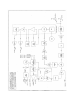
so as to provide a wide tuning range voltage to the frequency control varicaps located on
the VCO board. Frequency programming data for the receiver is sent to the synthesizer
chip from the Micro Controller via the a serial data line on SKD-18 under the control of
the Clock (SKD- 15) and Strobe (SKD- 17) lines
The local oscillator signal to the mixer is controlled by the Micro Controller through an
enable signal on SKD-8. This signal switches the supply to the local oscillator amplifier
and is used to enable or disable the receiver.
Provision is made for the optional injection of an external reference frequency. If this
option is selected CN3 is fitted.
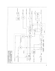
4.3. Power Amplifier Module
Refer:
PA Block Diagram BD004
PA Circuit Diagram: CSO16-1 (Band A to B)
CS006-1 (Band C to D3 )
CS007-1 (Band E to F)
CS013-1 (Band G to I)
CS008-1 (Band J to M)
CS009-1 (Band N to Q)
CS0010-1 (Band R to X)
CS014-1 (Band Nto Q 5W)
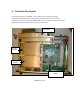
RF from the Exciter on CN1 is first attenuated by a 50 ohm pad which is used to provide
a good 50 ohm source impedance for the high power hybrid amplifier IC1. The RF is
amplified to between 5 and 13 watts at the hybrid 50 ohm output. The signal from the
hybrid is then matched by a broad band network to drive the low input impedance
associated with the final transmit power amplifier transistor TR1. The transistors low
collector impedance is then also matched back to 50 ohms by a broadband matching
network. Trimmer capacitors enable adjustment of the power amplifier over a wide
bandwidth so as to maintain good conversion efficiency. Prior to transmission a low loss
13 element elliptical low pass filter, filters out the unwanted harmonics to less than
-90dBc.
A dual directional coupler consists of coupled microstrip transmission lines S5, S6 and
S7 fabricated on the PCB artwork. The sampled RF energy is rectified to provide a
proportional DC voltage output on CN4-8 (FWD) and CN4-5 (REFL).
TR2 serves to switch the DC supply to the Hybrid under control of the PTT line from the
Micro Controller on CN4-2. A thermistor TS1 physically located on the PA heatsink is
connected to the Micro Controller via CN4-4/6