
User's Manual Chapter 5


Bandwidth CTCSS Option Peak Deviation (Hz)
narrow (12.SkHz spacing) YES 2150
NO 2400
medium (20kHz spacing-US) YES 4300
NO 4800
wide (25kHz spacing) YES 4300
NO 4800
Table 1 - Peak Deviation Settings
The setting of the peak deviation is done at 1 kHz for the standard build and 400Hz for the
E1A build. If the board is an EIA build this is noted on the motherboard. The modulation
balance for both builds is done at 400Hz. The transmitter modulating audio for this test is
connected to the WB/DC-FM input with JMP8 set to I-2. This input is located on the rear
of the MX800, on the Line I/O connector pin 13 of the DB15F connector. (Refer to
section 6.1.1 for additional help.)
Procedure
i) Disable the CTCSS if present. This is either done through the digital input port at
the rear or temporarily disabling it in the Channel Information Screen.
ii) PTT transmitter.
iii) Set the transmitter modulation frequency to lkHz, +10dBm, injected in through
the WB/DCFM input with JMP8 set to 1-2.
iv) Adjust the VCO Deviation digital potentiometer using MXTOOLS until the
correct deviation is obtained. (See Table 1- Peak Deviation)
v) Set the transmitter modulation frequency to 400Hz, +10dBm, injected in through
the WB/DCFM input.
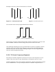
vi) Adjust the Reference Deviation digital potentiometer until the top of the
waveform is flat. If the waveform top droops increase the level (see Figure 1) and
if it peaks reduce the level (see Figure 2).
vii) Set the transmitter modulation frequency to either 400Hz / lkHz depending on the
build, +10dBm, injected in through the WB/DCFM input.
viii) Repeat steps iv) through to vii) until the correct peak deviation and modulation
balance is obtained.