
User Manual
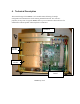
4.4. Micro Controller Board
Refer:
Block Diagram BD003 ( Rev A to I-D
BD005 (Rev I upwards)
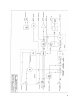
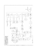
Circuit Diagram CS001-1/6
The MX800 Micro Controller Board has 4 main functions
Overall radio management
TX and RX signal processing
RF power control
User interface
4.4.1. Overall Radio Management
In addition to analogue signal processing circuitry the Micro Controller board
accommodates an 80C552 microprocessor IC1, a 64kbyte EPROM IC3, 32kbyte RAM
IC4, a 16kbyte EEPROM as well as address decoding, I/O latches and other
miscellaneous circuitry. The Micro Controller is responsible for ensuring that the radio
acts as programmed by the user. It stores the user-entered parameters for each channel in
EEPROM. This information includes RX and TX RF frequencies, RX and TX CTCSS
frequencies as weIl as RF output power and operating mode. An 8 channel analog to
digital converter allows the microprocessor to read 8 analogue values internal to the radio
which in conjunction with the digital inputs to the microprocessor allow the operating
status of the radio to be monitored and controlled. The following analogue items are read
Port Parameter
ADC0 Received Signal Strength Indication(RSSl)
ADC 1 Detected Discriminator output level
ADC2 DC operating voitage
ADC3 RX VCO tuning Voltage
ADC4 TX VCO tuning Voltage
ADC5 PA temperature
ADC6 PA forward power
ADC7 PA reflected power
The Micro Controller sends programming data to the synthesizer ICs on the Receiver and
Exciter modules each time the channel is changed as well as on PTT. This information is