
User Manual
connected to a RF test set displaying the frequency error. This procedure should be done
after the deviation alignment procedure has been done. Transmitter modulation should be
disabled.
To alter all channels at once use the 'Lock Data'•ption as described in the power setup
procedure. Alter the Reference Oscillator Frequency potentiometer until the channel is
"on frequency". Choose 'OK' to accept the changes made and then from the Channel
Screen choose 'Send Data to MX800'. This then saves the changes that you have made to
the radio.
To calibrate each channel individually make sure the 'Lock Data' option is not selected
and repeat the above procedure for each channel.
5.1.11.TX Line Input Level and Nominal Deviation Alignment
There are three manual potentiometers associated with the TX deviation on the
motherboard. These are set by injecting the correct audio levels and adjusting the
potentiometers. The transmitter modulating audio is to be connected to either the WB/DC-
FM input or the TX VF input as described in the procedures.
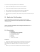
The required nominal deviation is dependent on whether the radio is narrow, medium or
wide. The following table lists the required level for each case:
Bandwidth FM Deviation (kHz)
narrow (12.5kHz spacing) 1.5
medium (20kHz spacing-US) 3.0
wide (25kHz spacing) 3.0
Table 2 - Nominal Deviation
The first potentiometer sets the TX Limiter Gain. The transmitter modulating audio for
this test is connected to the WB/DC-FM input with JMP8 set to 1-2. This input is located
on the rear of the MX800, on the Line I/O connector pin 13 of the DB 15F connector.
(Refer section 6.1,1 for additional help,)