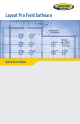
Layout Pro Field Software Quick Start Guide
SOFTWARE END USER LICENSE AGREEMENT IMPORTANT, READ THIS AGREEMENT CAREFULLY. BY INSTALLING OR USING ALL OR ANY PORTION OF THE SOFTWARE, YOU ARE ACCEPTING ALL OF THE TERMS AND CONDITIONS OF THIS AGREEMENT. YOU AGREE THAT THIS AGREEMENT IS ENFORCEABLE LIKE ANY WRITTEN AGREEMENT. IF YOU DO NOT AGREE TO ALL OF THESE TERMS AND CONDITIONS, DO NOT USE OR ACCESS THE SOFTWARE.
plicable law prohibits or restricts such restrictions); or (f) publicly disseminate performance information or analysis (including, without limitation, benchmarks) from any source relating to the Software. If the Software has been provided to you as embedded in any hardware device, you are not licensed to separate the Software from the hardware device.
sole liability (and your exclusive remedy) for any breach of this warranty shall be, in Licensor’s sole discretion, to use commercially reasonable efforts to provide you with an error-correction or work-around which corrects the reported non-conformity, or if Licensor determines such remedies to be impracticable within a reasonable period of time, to refund the license fee paid for the Software.
the United States government or any agency thereof requires an export license or other governmental approval at the time of export or re-export without first obtaining such license or approval; or (d) otherwise in violation of any export or import restrictions, laws or regulations of any United States or foreign agency or authority.
purposes and Defense Federal Acquisition Regulation Supplement 227.7202 for military purposes. The Software was developed fully at private expense. All other use is prohibited. 12.11.Third-Party Software. If designated in the Documentation, the Software may contain or be provided with certain Third-Party Software (including software which may be made available to you in source code form).
Table of Contents Getting Started ..........................................................................1 Working With Jobs......................................................................2 Starting a New Job ................................................................2 Settings and Preferences ............................................................3 Entering a Plan from a Blueprint..................................................4 Entering a Basic Plan....................................
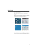
Getting Started Double-tap the Layout Pro icon on the data collector ([1]) or total station ([2]) desktop. With a data collector, the main menu ([3]) will appear instantly. With the onboard version, you will first have to level the total station and enter a few parameters (atmospheric, instrument parameters) before the main menu ([4]) displays. [1] [3] [2] [4] Note: In this guide, all screenshots showing a blue title bar originate from the onboard version of Layout Pro (i.e.
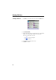
Working With Jobs Starting a New Job 1. Tap Jobs on the main menu. This opens the Jobs menu. 2. Tap Create New Job. 3. Using the keypad, key in a name for the job. The default name is the current date. Change it as you prefer. If you are using a data collector: – Tap to show the keypad – Tap to hide it. 4. Tap ok at the bottom of the screen. 5. Tap OK to continue.
Settings and Preferences From the main menu, tap Settings. The Settings & Preferences window allows you to set: • The instrument used ([1]) (with a data collector) or some instrument-related parameters (atmospheric parameters, calibration, DR target settings) with an onboard version. • The distance units used ([2]) • The format used to display values of distances, angles, etc.
Entering a Plan from a Blueprint Entering a Basic Plan 1. From the main menu, tap Plan. 2. Tap Input Plan to begin entering your plan. The following table shows the tools on the right side of the window that help you work with the display plan. Use this tool... to... Select from plan Show the whole plan Zoom in on active point Zoom out from active point Zoom to select area Set display options for labels (point names, etc.) 3. Enter or select a line start point. 4. Enter the length of the new segment. 5.
Adding an Arc to a Plan B P1 R H A α C P2 1. Select Enter an Arc from the Tools menu located at the bottom of the Enter Line window. 2. Choose the start point (P1) and end point (P2) of the arc. These points can be selected from the plan, or from the list of points, after selecting the corresponding option through the nearby scroll-down arrow button. You can also key in manually their numbers (if known). The selected points will then appear in red on the plan (see below). 3.
– Flip button: Tapping this button provides the other possible orientation for the arc. Tapping again this button will bring the arc back to its initial shape. 8. Tap Solve when you agree with the definition of the arc, which then appears on the plan. See example below. Remember, you can always step back while creating an arc (or a line) using the Back button when shown. Once the arc (or line) has been created, it can be deleted by tapping Undo at the bottom of the screen.
Creating Grid Points Additional points may be created on the plan by creating new lines based on existing points. The new points will result from the intersections of these new lines and possibly also with the other existing lines. 1. Tap Plan on the main menu. 2. Tap Create Grid Points. Below is an example of what you can see on the screen. 3. Set the New lines intersect with existing lines option as follows: – Check it on if you want to create points for every intersection.
Making Computations from your Entered Plan 1. Tap Plan on the main menu. 2. Tap Compute with Plan on the submenu. 3. Tap in the lower-right corner of the screen. This opens up a menu from which you can perform various computations: 4. Select Compute Area to compute the area and perimeter of a group of points: 5.
6. Select Compute Angle to compute the angle between any three points: 7. Select Compute Down & Out to compute a point’s down and out distance from a line that you specify: The blue line is the reference line. The red section that is overlaid on the blue line is the “down” portion. The red perpendicular line is the “out” portion.
Setting Up a Connected Total Station Before using a total station to perform a stakeout or survey, you must set up your total station (in the location you want to shoot from), level it, and turn it on. If you are using the onboard version of Layout Pro, nothing else needs to be done. If you are running Layout Pro on a data collector, connect the data collector to the total station using a serial cable or Bluetooth. Connection Settings Recommended Settings for Supported Total Stations To 1. 2. 3.
Station Setup If you choose to set up the total station over a marked point from the plan (Setup on a Known Point Location option, diagram [1] below), you will need to shoot one point. If you choose to set up the total station at a random location (Setup at Any Location option, diagram [2] below), you will need to shoot two marked points from the plan for angle and distance measurements, or shoot three points if only angles are to be measured.
5. If you chose Setup on a Known Point Location (see also diagram below): • Select the point from the plan where to set up the instrument ([1]). Set up the instrument at this location. • Select the reference point from the plan ([2]). Have a target placed over this point. • Check that everything is ready for a shot ([3]), aim the instrument at the target and then tap Shoot. • After Layout Pro has reported a valid measurement ([4]), tap Finish. Station setup is now complete.
6. If you chose Setup at Any Location (see also diagram below): • Set up the instrument at any convenient location from which you have a good view of the two reference points. • Select the first reference point from the plan ([1]). Have a target placed over this point. Aim the instrument at this point and shoot it ([2]) • Repeat the first step for the second reference point used ([3] and [4]). You then get screen [5] on which the instrument position is reported to have been determined.
Performing Stakeout Stakeout Using an Entered Plan 1. When everything is set up correctly (see Station Setup on page 11), tap Points from the Layout menu. 2. From the Layout Pro display, select the point you want to stake. The horizontal angle and horizontal distance to that point from the total station are displayed. 3. Tap Next. Layout Pro calculates and displays the value and direction of the angle –measured from the last shot– the instrument should be rotated by to be aligned with the stake point. 4.
6. Guide the rod holder closer to the stake position and reshoot. You can re-shoot as many times as necessary until the rod is within an acceptable range of the correct position. Tap Stk> when an acceptable position is established. 7. Tap Store & Next Pt to store the position of the rod holder and to go back to the Define Stake Point screen from which you can select the next point you want to stake. Stakeout Using a Reference Line 1.
• If you choose Stake Out Points and tap Next, a screen appears that explains the down and out method of measuring stake points (see screen below). Key in the down and out positions for the point you want to stake.Tap Next. Have the rod holder move to where you think the stake point should be. Aim your instrument at the person and tap Shoot. You can re-shoot as many times as necessary until the rod person is positioned correctly. • If you choose Show Position, no entries are made.
Stakeout Using a Reference Arc 1. When everything is set up correctly (see Station Setup on page 11), tap Arc from the Layout menu. 2. Define the reference arc or select an existing one from the plan, using one of the four options below. B P1 R c A [1] P2 P1 [2] P2 P3 P2 P1 [3] • Two points on the arc & radius (see diagram [1]): Select the start (P1) and end (P1) points from the plan, key in the radius (R) and choose the short (A) or long (B) section.
3. Tap Next. You can choose between Stake Out Points and Show Position (see screen below). • If you choose Stake Out Points and tap Next, a screen appears that explains the down and out method of measuring stake points (see screen below). Shoot and adjust as required. • If you choose Show Position, no entries are made. Simply take a shot at the rod and the position is shown in relation to the reference arc. See example below.
Measuring Features 1. When everything is set up correctly (see Station Setup on page 11), tap Measure Features from the Layout menu. You may choose to measure either points or a line. 2. Enter a description (if desired) for the line or point being measured. Tap Shoot. 3. Repeat as necessary until all points have been measured. Importing/Exporting Data Tap Data Center on the main menu. From the submenu, you can: • Import DXF jobs or points.
Layout Pro Field Software Quick Start Guide SPECTRA PRECISION Survey Support: Email: support@spectraprecision.com technical@ashtech.com US & Canada: +1 888 477 7516 Latin America: +1 720 587 4700 Europe, Middle East and Africa: +49 7112 2954 463 Australia: +61 7 3188 6001 New Zealand: +64 4 831 9410 Singapore: +65 3158 1421 China: 10 800 130 1559 Contact Information: SPECTRA PRECISION DIVISION 10355 Westmoor Drive, Suite #100 Westminster, CO 80021, USA www.spectraprecision.