ProFlex 800 ™ Getting Started Guide Backpack Configuration
Copyright Notice Copyright 2012-2013 Trimble Navigation Limited. All rights reserved. P/N631671-01 rev B, February 2013 Trademarks All product and brand names mentioned in this publication are trademarks of their respective holders. Limited Warranty Terms and Conditions Product Limited Warranty.
What is ProFlex 800? .................................................................1 Scope of this Guide ....................................................................2 System Components Overview......................................................3 ProFlex 800 Basic Supply ......................................................3 Standard Accessories .............................................................4 Optional Accessories ..............................................................
English
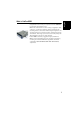
Congratulations! You have just acquired a ProFlex 800 GNSS receiver from Spectra Precision! GNSS have revolutionized control surveys, topographic data collection, construction surveying, marine surveying and machine guidance and control. Purchasing the right tools for a professional job is essential in today's competitive business environment. Learning to put these tools to work quickly and efficiently will be the focus of this manual.
Scope of this Guide English This guide is designed to help you rapidly familiarize yourself with your new equipment. It is more particularly focused on land surveying applications, when the ProFlex 800 is carried in a backpack and used with a data collector and survey field software. However, other applications (machine guidance and marine surveying) are suggested in this guide, for example when describing the receiver (connectors, available accessories, etc.
The tables below provide an overview of the different key items composing the ProFlex 800. The list of items is intentionally limited to those more particularly required to operate a temporary base, and a rover in backpack configuration. The complete list of items is provided in the ProFlex 800 Reference Manual. Depending on your purchase and based on the type of survey you wish to perform, you may only have some of the listed items.
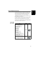
English Standard Accessories (Can also be ordered separately as spare parts using part numbers mentioned below.) Item Cellular antenna (quad-band) 111397 Bluetooth antenna 111403 7.4 V-4.6 Ah Li-ion Battery Pack (rechargeable) 111374 USB Host-to-Device Cable, 0.2 m Makes ProFlex 800 a USB device.
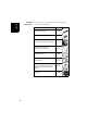
GNSS Antennas Item Part Number ASH-661 L1/L2/L5 GNSS antenna, gain: 38 dB 802135 ASH-660 L1 GNSS antenna, gain: 38 dB 802133 English Optional Accessories Picture UHF Antennas Item Part Number Whip antenna, TNC adapter, 410-430 MHz C3310190 Whip antenna, TNC adapter, 430-450 MHz C3310196 Whip antenna, TNC adapter, 450-470 MHz C3310188 Picture Transmitter Kits Item ADL Vantage ADL Vantage Pro Part Number 87330-00: ADL Vantage Kit, 430-470 MHz, 4W 87330-20: Accessory kit, 430-450 MHz 87330
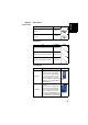
Other Accessories English Item Part Number Survey Backpack Kit, includes: • Backpack • 7.4 V-4.6 Ah Li-ion Battery Pack (rechargeable) • GNSS cable with push-pull system consisting of PP-m/TNC-m 50-Ohm coaxial cable, 890309 1.50 m, and PP/TNC-m 50-Ohm coaxial cable, 0.75 m. • Range pole for UHF antenna (includes 0.50meter pole with 5/8” female adaptor, TNC receptacle and TNC-female/TNC-female cable extension, 0.
English Equipment Description & Basic Functions Front View From left to right: Bluetooth Antenna A coaxial female connector (reverse SMA type) allowing you to connect a Bluetooth antenna for wireless communication with a field terminal or other device. Cellular Antenna A coaxial female connector (SMA type) allowing you to connect a cellular antenna. A cellular antenna is required when the ProFlex 800 sends or receives RTK or differential corrections data via its internal cellular modem (GSM).
English USB Host & Device A nine-contact female connector (Fischer type). Depending on how it is configured, the USB port can be used in two different ways: 1. For a USB host, such as a mass storage device using optional device cable P/N 702104. 2. For a USB device allowing ProFlex 800 to be seen as a disk from the computer connected to this port. In this configuration, files can be transferred between the ProFlex 800’s internal memory and the computer using the USB cable provided (P/N 702103).
Log Button Press this button briefly to start recording raw data on the selected storage medium. Another short press on this button will immediately stop raw data recording. Scroll button Press this button briefly to scroll through the different pages of information viewed on the screen. If an alarm is reported on the display screen, a short press on the Scroll button will acknowledge the alarm.
English GNSS Input #1 A TNC coaxial female connector [2] allowing you to connect a GNSS antenna to the receiver via a coaxial cable. Serial Data Ports These are all Fischer, seven-contact, female connectors, each allowing a serial connection to an external device. • Ports F [3] and B [4] are both RS232-only ports • RS232/422 Port A [5] is a switchable RS232/RS422 port (Default is RS232).
A TNC coaxial female connector [8] for applying an external reference clock. (Connector [8] is missing on the rear view above.) CAN 2.0 Bus A Fischer, five-contact, female connector [9] allowing you to connect the ProFlex 800 to external, NMEA2000-compatible equipment via CAN bus. (For future use.) Earth Terminal A screw terminal [10] for connecting the receiver chassis to Earth.
English Battery Model & Battery Compartment The battery used is a 7.4-V DC - 4600 mAh rechargeable battery. It is a standard model used in many camcorders. The battery is housed in a battery compartment accessible from above the ProFlex 800. The compartment door can be opened by lifting and then turning the quarter-turn finger screw counter-clockwise.
These button combinations are summarized in the table below: Button Combination ProFlex 800 State Function Power+Log+Scroll OFF Restores Factory Settings. Power+Scroll Initiates firmware update from USB key. OFF 13 English connected or the key does not contain a firmware upgrade, then the process will abort after a few seconds. Because data has to be decompressed on the USB key during upgrades, the USB key must be unlocked, with at least 100 MBytes of free memory, before starting the upgrade.
Charging Batteries Before Use English Make sure the battery is fully charged for each ProFlex 800 you will be using in the field. Follow the instructions below to charge a battery. Removing the Battery from the ProFlex 800 Unless the battery has already been taken out, do the following: • Open the battery trapdoor, accessible from above the ProFlex 800, by lifting and then turning the quarter-turn finger screw anticlockwise.
English 1 2 [1] MED HI MAX [3] [4] [5] [6] MED HI MAX MED HI MAX MED HI MAX Inserting the Battery in the ProFlex 800 [2] • Plug the adapter into an AC outlet. Battery charging starts immediately. For a low battery that’s being charged, you will first see the three LEDs switch on and off, one after the other, followed by a short period of time when none of the LEDs is on (see [3]). After about two hours of charging, the MED LED will stay on [4].
Display Screens English If you press the Scroll button several times, you will see the following displays successively. Power-On Screen When you power on the receiver, the Ashtech logo appears on the screen. It is displayed until the receiver has completed its auto-test (this takes about 30 seconds). Then the General Status screen is displayed. General Status Screen An example of General Status screen is shown below.
• : Data link icon [5]. This icon is displayed only when corrections are received. • Age of corrections [6], in seconds. This value is displayed when corrections are received and only after base station information has been received (Position status is at least “DGPS”). • Raw data logging icon [7]: Data recording through front panel Log button: – Blinking: Raw data logging in progress – Fixed: No raw data logging in progress. ATL data recording for advanced diagnosis.
English • GSM module (modem) status [12]. This may be one of the following icons: Icon Blank Definition Modem turned off. Blinking icon: Modem turned on but not initialized yet. Indicates signal strength at modem antenna input. Fixed icon: Modem turned on and initialized (ready for a connection). Indicates signal strength received at modem antenna input. The higher the number of bars, the better the signal. This icon will show four dots at the bottom when the input signal is zero.
About the “*” symbol: • It can only appear at the end of the first or third line. • Where placed, it indicates that this storage medium is used for data logging. What if there is no USB mass storage device connected to the receiver? • Parameters relevant to the USB key size and space used and available are void (three dots displayed instead). • Number of files is forced to “0”.
English reference position assigned to the base. See screen example below for a rover delivering WGS84 coordinates. The upper line contains the same information as in the upper line of the General Status screen. A new press on the Scroll button will take you to the ATL Recording screen (see below).
English You don’t normally have to record ATL data, but if for troubleshooting purposes, the Technical Support asks you to do so, then proceed as follows: • Press the Log button (left-hand button). This will cause the receiver to start recording ATL data on the specified storage medium.
English ATL Recording Screen Scroll button Clean up internal memory? No Yes No Delete all G-files? Yes Delete all files? No Format memory? Yes Yes No Yes Confirm? In progress... No Back to General Status Screen Screen Backlight Data Transfer Screen 22 The screen backlight is automatically turned off if no key is pressed for 1 minute. When the backlight is off, a short press on the Scroll button will turn it back on. The Scroll button will then recover its usual functions.
English Mounting Options Backpack Mount The ProFlex 800 is secured in a backpack when used as a rover for land surveying applications. Tripod Mount In land surveying applications, when used as a roaming base mounted on a tripod, the ProFlex 800 can be secured on one of the legs of the tripod using the lug located on its bottom side. The lug may be secured onto the chassis in two different ways allowing the receiver to be installed either with its front panel upwards or sideways (recommended).
Temporary RTK Base Setup English Prerequisites • You will need a tripod and a tribrach (not provided) to install the base. You will also need an antenna extension pole fitted with a 5/8” male adaptor (not provided but available as an accessory). • For a long-range radio link, i.e. more than 1 mile or 1.6 km, for which the radio antenna should be placed as high as possible, it is good practice to install the antenna on top of an antenna pole secured on a tripod (neither of these items is provided).
Radio Antenna ADL Vantage or ADL Vantage Pro Transmitter Power Port A To GNSS Antenna ProFlex 800 Base Cable P/N 802143 Fuse (4 A) + SAE External 9-30 V DC Power Source Pacific Crest Data/Power Cable (A00630) 25 English The connection diagram is as follows. The use of port A is recommended on the receiver side. However, any of the other serial ports may be used as well.
External Battery Used Power (No power limitation) GNSS Input To GNSS Antenna Radio Antenna ProFlex 800 Base Cable P/N 802143 Fuse (4 A) + External 9-36 V DC Power Source Internal Battery Used (Radiated power To limited to 100 mW) GNSS Antenna Port A Radio Antenna GNSS Input English Embedded Transceiver (ADL Foundation) ProFlex 800 Base 26
Prerequisites 1 2 • Insert a freshly charged battery into the ProFlex 800. • Use a range pole fitted with a 5/8” male adaptor at the upper end (not provided). • Mount the GNSS antenna at the top of the range pole. • Connect coaxial cable P/N P076510A to the GNSS antenna. • If a radio link is used with the base, your rover should normally have been fitted with the radio receiver kit that matches the reception band covered by the radio transmitter used at the base.
English compartment, down to where the rear panel of the receiver will be located once placed in the backpack. • Communication with field terminal: If Bluetooth is used, no special cable is needed. If wired communication is used, pass the Fischer end of serial data cable P/N 700461 (provided) through a velcro flap, and again make it run along the inner edge of the compartment, down to where the rear panel of the receiver will be located once placed in the backpack. [3] [4] 3.
If you are using an external cell phone for acquiring RTK corrections, place it in the mesh pocket [6] located on the left-hand belt of the backpack. [6] 29 English such a way that the antennas can pass through the slots designed into these straps. 8. Turn on the ProFlex 800 and close (zip) the compartment. 9. Place the backpack on your back. 10.Connect the free ends of the quick-release coaxial cables together. This connects the GNSS antenna to the receiver. 11.
Logging Raw Data English Starting/Stopping Raw Data Logging You simply need to use the Log button to start and stop raw data logging. Later, you will however need to do the following manually: 1. Downloading phase (if appropriate, rename the raw data files collected on each site). 2. Post-processing phase: Manually correct all computed elevations for the antenna height. By default, raw data is logged to the receiver’s internal memory.
Using the USB Cable Provided • Connect the USB cable provided (P/N 702103) between the office computer and the receiver’s USB port. The receiver is then seen as a USB device from the office computer • Using Windows Explorer on your office computer, browse the receiver’s internal memory for the raw data files. • Copy/paste the files to your project folder.
Index A AC/DC power supply kit 4 Alarm status 17 Alarms 9 Antenna (GNSS) 5, 27 AUTO 16 B GLONASS 1 GNSS input #1 10 GNSS input #2 11 GPRS 27 GSM antenna 4, 7 GSM status 18 H Backlight 9 Backpack 23, 27 Backup battery 12 BASE 16 Battery (external) 24 Battery (insert) 15 Battery (remove) 14 Battery charger 4 Battery icon 17 Battery model 12 Bluetooth 28 Bluetooth antenna 4, 7, 28 Bluetooth identifier 19 Bluetooth status 18 Bottom mount 23 Buzzer 11 Host cable (USB) 4 C PacCrest transmitter (connection
SMA 7 Standalone (raw data logging) 30 Status (position) 16 T Tribrach 24 Tripod 24 Tripod mount 23 U UHF input 10 USB port 8 USB status 18 V Velcro 27 Z Z-Blade 1
ProFlex™ 800 Getting Started Guide Contact Information: SPECTRA PRECISION DIVISION 10355 Westmoor Drive, Suite #100 Westminster, CO 80021, USA www.spectraprecision.com Rue Thomas Edison ZAC de la Fleuriaye, BP 60433 44474 Carquefou Cedex, FRANCE © 2012-2013 Trimble Navigation Limited. All rights reserved. Spectra Precision is a Division of Trimble Navigation Limited. Spectra Precision and the Spectra Precision logo are trademarks of Trimble Navigation Limited or its subsidiaries.