ProFlex 800 CORS ™ Getting Started Guide CORS Reference Station
Copyright Notice Copyright 2012-2013 Trimble Navigation Limited. All rights reserved. P/N631673 rev B, July 2013 Trademarks All product and brand names mentioned in this publication are trademarks of their respective holders. Limited Warranty Terms and Conditions Product Limited Warranty.
Table of Contents What is ProFlex 800 CORS? .................................................................1 Hardware Description..........................................................................3 System Components Overview .................................................3 ProFlex 800 CORS Basic Supply .........................................3 Standard Accessories .........................................................3 Optional Accessories .....................................................
Home Tab ...........................................................................38 Status Bar and Units Used ...................................................39 Distance Units .................................................................41 Angle Units .....................................................................41 Time Units ......................................................................42 Setting a CORS Reference Station......................................................
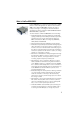
What is ProFlex 800 CORS? ProFlex 800 CORS is a rugged and high-performance CORS reference station. Designed as an extension of the ProFlex 800 receiver, ProFlex 800 CORS integrates the best of today’s technologies, including the exclusive Z-Blade™ algorithms and multi-constellation (GPS+GLONASS+QZSS+ GALILEO+SBAS) capabilities.
• • • • 2 makes it possible to access various sources of data from different base stations through a single Internet connection, as well as efficiently protect these sources of corrections from unauthorized users. The embedded NTRIP caster allows you to organize a network of up to 10 different mount points (each of them receiving corrections from an NTRIP server) and up to 100 users given the ability to receiver corrections through these mount points. Smooth integration of meteorological and tilt data.
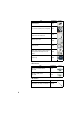
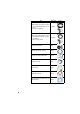
Hardware Description System Components Overview The tables below provide an overview of the different key items composing the ProFlex 800 CORS. Depending on your purchase, you may only have some of the listed items. Please refer to the packing list for an accurate description of the equipment that has been delivered to you. Spectra Precision reserves the right to make changes to the items listed below without prior notice.
Item Bluetooth antenna Part Number Picture 111403 7.4 V-4.6 Ah Li-ion Battery Pack (rechargeable) 111374 USB Host-to-Device Cable, 0.2 m Makes ProFlex 800 a USB device. Ethernet adaptor cable Serial data cable 702104 702426 700461 AC/DC Power Supply Kit (includes external AC adapter, battery charger and cable extension for 802064 powering ProFlex 800 directly from the AC adapter) Transport bag 206490 Optional Accessories GNSS Antennas.
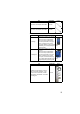
Item Part Number Whip antenna, TNC adapter, 430-450 MHz C3310196 Whip antenna, TNC adapter, 450-470 MHz C3310188 Picture Transmitter Kits. Item ADL Vantage ADL Vantage Pro Part Number 87330-00: ADL Vantage Kit, 430-470 MHz, 4W 87330-20: Accessory kit, 430-450 MHz 87330-10: Accessory kit, 450-470 MHz Each accessory kit includes a unity-gain antenna, a range pole mount, a tripod mount system, a battery accessory kit (without the battery) and a Vantage/Vantage Pro programming cable.
Item Part Number GNSS Marine 30-meter Cable Kit, consists of: • Low-loss LMR-240 GNSS cable, TNC-m/ P076464A TNC-m • Antenna mounting bracket GNSS Marine 10-meter Cable Kit, consists of: • Low-loss RG223 GNSS cable, 10 meters, P0101393 TNC-m/TNC-m • Antenna mounting bracket Vertical antenna extension 103717 TNC/TNC antenna cable, 10 meters 700439 External power cable for GNSS receiver 802143 Y-shaped power cable 702501 Universal cable 702443 USB cable, device to PC 702103 ADL Vantage (Pro) t
Firmware Upgrades Item GLONASS GALILEO GPS L5 Unlimited RTK Fast Output Flying RTK Embedded NTRIP caster GSM Equipment Description & Basic Functions Part Number 680500 680655 680656 680502 680527 680635 680636 680528 Front View From left to right: Bluetooth Antenna. A coaxial female connector (reverse SMA type) allowing you to connect a Bluetooth antenna for wireless communication with a field terminal or other device. Cellular Antenna.
USB Host & Device. A nine-contact female connector (Fischer type). Depending on how it is configured, the USB port can be used in two different ways: 1. For a USB host, such as a mass storage device using optional device cable P/N 702104. 2. For a USB device allowing ProFlex 800 to be seen as a disk from the computer connected to this port. In this configuration, files can be transferred between the ProFlex 800’s internal memory and the computer using the USB cable provided (P/N 702103). Display Screen.
• It is on and green when the ProFlex 800 is on, regardless of whether it is powered from the internal battery or an external power source. • It is blinking red when the sleep mode has been enabled and the receiver is currently running a session. With the sleep mode enabled, the receiver is idle between any two sessions, as if it were virtually turned off, and the power LED is also turned off during this time. Log Button. Press this button briefly to start recording raw data on the selected storage medium.
GNSS Input #1 . A TNC coaxial female connector [2] allowing you to connect a GNSS antenna to the receiver via a coaxial cable. Serial Data Ports. These are all Fischer, seven-contact, female connectors, each allowing a serial connection to an external device. • Ports F [3] and B [4] are both RS232-only ports • RS232/422 Port A [5] is a switchable RS232/RS422 port (Default is RS232).
GNSS Input #2. A TNC coaxial female connector [8] for applying an external reference clock. (Connector [8] is missing on the rear view above.) CAN 2.0 Bus. A Fischer, five-contact, female connector [9] allowing you to connect the ProFlex 800 to external, NMEA2000-compatible equipment via CAN bus. (For future use.) Earth Terminal. A screw terminal [10] for connecting the receiver chassis to Earth. Electric Isolation.
Battery Model & Battery Compartment The battery used is a 7.4-V DC - 4600 mAh rechargeable battery. It is a standard model used in many camcorders. The battery is housed in a battery compartment accessible from above the ProFlex 800. The compartment door can be opened by lifting and then turning the quarter-turn finger screw counter-clockwise. The battery will automatically operate as a backup power source for the receiver if for some reason the external DC source used is removed from the DC power input.
a few seconds will cause the ProFlex 800 to start a firmware upload process. If there is no USB key connected or the key does not contain a firmware upgrade, then the process will abort after a few seconds. Because data has to be decompressed on the USB key during upgrades, the USB key must be unlocked, with at least 100 MBytes of free memory, before starting the upgrade.
Charging the Battery The battery charger comes with a separate universal AC adapter fitted with a 1.5-m output cable. The AC adapter includes a choice of four different, detachable plug types. Follow the instructions below to operate the charger. • Choose the plug type that is suitable for your country. • Secure that plug on the AC adapter. • Connect the cable from the AC adapter to the battery charger.
Note that once it is properly secured, the trapdoor pushes the battery against the bottom of the compartment to ensure electrical connection of the battery to the ProFlex 800. Display Screens If you press the Scroll button several times, you will see the following displays successively. Power-On Screen When you power on the receiver, the Ashtech logo appears on the screen. It is displayed until the receiver has completed its auto-test (this takes about 30 seconds).
are also used to compute an SDGPS solution of the base position. This solution is permanently available on the position computation screen (see Position Computation Screen on page 18). • Raw data logging icon [5]: Data recording through front panel Log button or using Recording submenu in the Web Server: – Blinking: Raw data logging in progress – Fixed: No raw data logging in progress. Data recording through sessions: – Blinking: Raw data logging in progress – Fixed: No raw data logging in progress.
Icon Definition Blinking icon: Modem turned on but not initialized yet. Indicates signal strength at modem antenna input. Fixed icon: Modem turned on and initialized (ready for a connection). Indicates signal strength received at modem antenna input. The higher the number of bars, the better the signal. This icon will show four horizontal bars at the bottom when the input signal is zero. The symbol shown in the upper-left corner stands for “2G”.
• Third line: Percentage of free space on the USB mass storage device. • Fourth line: Number of files currently stored on the USB mass storage device. Right screen: • First line: Total space occupied by the files currently stored in the internal memory. • Second line: Nominal size of the internal memory. • Third line: Total space occupied by the files currently stored on the USB mass storage device. • Fourth line: Nominal size of the USB mass storage device.
of the reference position assigned to the base (not a computed position). See example below. The upper line contains the same information as in the upper line of the General Status screen. A new press on the Scroll button will take you to the ATL Recording screen (see below). Memory Management Screen From the ATL Recording screen, press the Scroll button to access the Memory Management screen.
You don’t normally have to record ATL data, but if for troubleshooting purposes, the Technical Support asks you to do so, then proceed as follows: • Press the Log button (left-hand button). This will cause the receiver to start recording ATL data on the specified storage medium.
Data Transfer Screen For more information on the screen displayed when downloading files, refer to the ProFlex 800 Reference Manual. How to Safely Power the ProFlex 800 CORS The setup below is recommended to power the ProFlex 800 CORS as it provides efficient protection from possible power cuts. The slide switch located in the battery compartment should be set to ON (pushed to the right) to make sure the receiver will start automatically after a power shutdown.
Introduction to ProFlex 800 CORS Configuration Introductory Notes This section more particularly focuses on how to successfully configure the ProFlex 800 CORS using the ProFlex Web Server. A few status screens are also presented. It is assumed that you have all the information needed1 to perform an IP connection from your computer to the ProFlex 800 CORS.
2. Opening the Configuration tab to enter the general settings common to any base or reference station. 3. Still on the Configuration tab, entering the settings specific to the ProFlex 800 CORS.
8:00 9:00 Session No. 1 (A) 10:00 Session No. 2 (B) Session No. 3 (C) 11:00 12:00 Session No. 4 (D) Raw data files (G-files) covering one hour each Sessions can be created either automatically (in this case they are all of the same duration), or created individually through a manual procedure. The two methods can be combined. For example, sessions can first be created automatically and then adjusted manually and individually, if necessary.
For example, with Reference Day=33 (Feb 2), if the current day is 30 (Jan 30), the station will start the first session only in three days, whereas if the current day is 51 (Feb 20), the station will start the programmed sessions on that day. If you do not need to postpone the execution of the sessions, keep the default value (1) for this option. • Offset per Day (in minutes and seconds): This option is specifically designed for users who wish to have the same sky view of the GPS constellation every day.
receiver to automatically delete the oldest G-file when the amount of available free memory (in the selected storage device) falls below 15 Mbytes. Converting/ Deleting G-Files Collected During Sessions G-files can be converted to Rinex 2.11 or 3.01, with or without the Hatanaka option. This will happen only if ATOM navigation data are included in the G-file (the conversion will otherwise fail). The receiver can automatically complete the RINEX file header while converting G-files to RINEX files.
Root Sitename Year e.g. 1001 e.g. 2010 Day 1 e.g. 121 G-files and/or converted files Day 2 122 G-files and/or converted files Organizing the storage of the files is simply obtained by typing the appropriate codification of the subdirectories in the field named Sub-directory Name Format. This field uses a specific syntax with case-sensitive characters.
External FTP Server IP address or server name ProFlex 800 (Client) Internet Ethernet Raw Data Files End users The reference station being the client for this transfer, you need to enter the IP address (or host name) and IP port of the remote FTP server, and also enter the login and password that will let the receiver upload its files to the server without any problem. You can also sort the files while transferring them to the FTP server.
• Permanently, as a second repository for all the files collected by the CORS station. Recording Raw Data Outside of Any Sessions Raw data recording can also take place outside of any sessions. What’s more, it can take place simultaneously with data recording performed through the programmed sessions. This alternate recording capability can be controlled through the Configuration - Recording submenu in the ProFlex Web Server.
Embedded NTRIP Caster Introduction The Embedded NTRIP Caster allows you to build your own NTRIP network solution around the ProFlex 800 CORS station. The embedded NTRIP caster can handle a total of 100 users and 10 mount points. The number of 100 users should be understood at the total number of possible users, irrespective of the mount points they are using. For example, if 90 users are connected to mount point n, then only a total of 10 users can be connected to any of the other mount points.
Reference Position NTRIP servers 1 and 2 may be connected to the embedded NTRIP caster (local host) or to an external NTRIP caster. Base Differential Stream 1 NTRIP Server 1 Port P (IP client) Differential Stream 2 NTRIP Server 2 Port Q (IP client) NTRIP Caster (IP Server) ProFlex 800 (Ethernet Port) Internet Other NTRIP casters...
Reference Position Base Differential Stream 1 or 2 NTRIP Server 1 or 2 NTRIP Caster Port P or Q (IP client) (IP Server) ProFlex 800 (Ethernet Port) Internet NTRIP Clients (Users) (IP clients) NTRIP Caster Control & Monitoring The ProFlex Web Server provides an easy way to remote control and monitor the Embedded NTRIP caster.
• The Mount Points submenu allows you to define each of the possible 10 mount points of the NTRIP caster. Choosing the name of a mount point is important: – it is through that name that NTRIP servers can connect to the NTRIP caster. – it is through that name that users can choose which base station they want to receive correction data from.
Map The Web Server provides a map of the NTRIP caster network using different colors to show the location of the caster, of the NTRIP servers (bases) and of the different users. Protecting Mount Points Protecting mount points may be done in an indirect way, as explained below: • Not assigning a mount point to any of the declared users implies that this mount point is accessible to anyone who can make an Internet connection to the NTRIP caster.
SMTP Server ProFlex 800 Administrator Computer Alarm email Internet Ethernet Alarm email You may choose between three different levels of notification: • Full notification. Each of the following events will generate an email: – “High” and “medium” alarms – Receiver powered on – Power shutdown causing the receiver to operate from its internal battery. • Standard notification.
receiver memory and directory via an IP connection, using the FTP communication protocol. In this case, end users should be given read access (through a user profile) to the directory containing the raw data files collected by the receiver. Alternatively, as the owner of the station, you may have to perform remote maintenance operations in the receiver memory. This connection gives you full read/write control on the specified directory and child directories.
also be saved as a D-files, in which case the D-files are saved in the same subdirectory as the corresponding G-files. Sensor data can also be output through the NMEA XDR message type. External sensors can be connected to the ProFlex 800 using multi-function serial cable P/N 702450 (3 meters in length). This cable has bare wires at one end, and a circular, sevencontact connector at the other end. The pinout is as shown in the diagram below.
First Steps With the Web Server Home Tab The Web Server Home tab appears after you have typed the correct IP address in the Address box of your web browser and pressed the Enter key. In the right-upper corner of the window, you have access to the on-line help (HELP link) and to technical support (SUPPORT link). You can also change the language of the Web Server interface. This will simultaneously change the language of the Help files accessible through the HELP link.
these parameters. For your information, the third column indicates the relevant $PASH commands. Parameter Receiver serial number Owner name Company name Phone Email Designation $PASH Hardware-coded receiver serial number $PASHQ,RID Owner name Name of the company operating the receiver Contact phone number Contact email $PASHS,WEB,OWN $PASHS,WEB,OWN $PASHS,WEB,OWN $PASHS,WEB,OWN (The last four parameters can be changed from the Administrator menu on the Configuration tab.
By column from left to right: Column #1 Mode Position Station ID Age Column #2 Lat Long Height Heading Column #3 HRMS VRMS HDOP VDOP Column #4 GPS GLONASS SBAS GALILEO QZSS Column #5 Battery Receiver operating mode (“Base”, “Rover”, etc.) Type of position solution currently available from the receiver (“No position”, “Autonomous”, “DGPS”, “S-DGPS”, “RTK Fixed”, “RTK Float”) If a base: • 0 to 4095 for a station transmitting ATOM or RTCM3.x corrections • 0 to 1023 for a station transmitting RTCM2.
FTP Push Column #8 Date Time Alarm report Indicates whether the recorded raw data files are uploaded to an external FTP server (“On”) or not (“Off”). Current date (YYYY-MM-DD) Current local or UTC time (hh:mm:ss) according to the setting below. Blank area if no alarm has been detected. “Alarms” displayed if an alarm has been detected in the receiver, followed by the number of raised alarms, between brackets (x). A click on “Alarms” will open the Status-Alarms web page to list this or these alarms.
Angle Unit Latitude Format Used Deg. Min. DD°MM’ SS.SSSSS” N or Sec. DD°MM’ SS.SSSSS” S Longitude Format DDD°MM’ SS.SSSSS” E or DDD°MM’ SS.SSSSS” W Where: • N for North, S for South; E for East, W for West • “D..” for degree digits, “M..” for minute digits, “S..” for second digits When typing in a latitude or longitude, leading and trailing zeroes can be omitted. Degree (°), minute (’) and second (”) symbols can be omitted as well. For example, typing 5 6.45 N is a valid entry for 5° 06.450000’ N.
Setting a CORS Reference Station How to Start • Open the Web Server’s Configuration tab. The first time you click on this tab, the Web Server will ask you to log in as the administrator. Only the receiver administrator is authorize d to access the Configuration tab. You are allowed to change the destination of a receiver (e.g. it is currently a rover and you want to change it into a base).
– Antenna Radius: In case of a “Slant Height” measurement, enter the antenna radius (this is a manufacturer specification), taking care to enter this parameter in the selected distance unit. See also the diagram below for more information. – SHMP Offset: In case of a “Slant Height” measurement, enter the SHMP offset (this is a manufacturer specification) taking care to enter this parameter in the selected distance unit. See also the diagram below for more information.
• All ATOM and Ashtech legacy raw data message types are listed below. Format ATOM Ashtech legacy Message types NAV, PVT, ATR, DAT, EVT, RNX DPC, SAL, SAG, SAW, SNG, SNV, SNW, ION, SBD, MPC, PBN (Typically, a G-file should contain NAV, RNX and ATR data to guarantee successful conversion of the file into RINEX files. NAV provides navigation data, RNX observations data, and ATR external sensor data.
defined by the Recording Interval parameter on the Sessions - Scheduling web page (see Programming Sessions on page 46). The value you might enter on the Raw Data web page for these messages would anyway be ignored. It would even be overwritten with the value given to Recording Interval when the first session starts. • Click on the Configure button to save all the changes made. The concatenation of the selected messages will constitute the G-files saved in the receiver (internal memory or USB device).
Clicking in a row inside the table allows you to edit the session individually. The changes are then entered by clicking on the Manual Set button Note that the Use button is checked by default, which means data recording is allowed during the session. Starting Sessions & Managing Raw Data Files To start the execution of the programmed sessions on the current day, do the following: • Click on Sessions - Settings • Enable the Run Sessions check box.
• Check the Ring File Memory option. This will result in an unlimited operating time for the station while using a finite memory size. • Data Type recalls the type of raw data collected through sessions. • You may want to save receiver power between sessions when those are separated by more than 15 minutes of idle time. If so, check the Power Off.. Between Sessions button. Remember power will be applied automatically to the receiver 15 minutes before the beginning of the next session.
• Using the different fields in the Transfer to external FTP Server pane, choose whether you want the receiver to automatically transfer the collected raw data files (original and/or converted files) to an external FTP server. If so, activate the Automatic Transfer option and enter the identification parameters of the FTP server: – FTP Server, Port: FTP server IP address/hostname and IP port – Login, Password: Connection profile that gives the receiver the rights to upload data to the FTP server.
– SMTP Server and SMTP Port: Enter respectively the name and port of the server in charge of routing the emails issued by the receiver. The SMTP server you need to use depends on the network the receiver is connected to. In most cases, it is the one of your Internet Service Provider. “25” is the well known port number for communications using the SMTP protocol. – Username and Password: Give identification information allowing you to send emails to the specified SMTP server.
– In the Memory Location field, choose the memory the FTP server will give access to. – In the FTP Path field, specify the path to the subdirectory (in the selected memory) the FTP server will have access to (syntax: /subdirectory/.../ subdirectory/). The first and last slashes are optional. – Administrator Username and Password fields: Username and password for the administrator of the embedded FTP server (default: “admin”, “changeme”). Not to be confused with the administrator of the ProFlex Web Server.
– Set the port’s Baud Rate and RTS/CTS – Enter the Initialization String and Trigger String. These are parameters specific to the sensor used. They should normally be found in the manufacturer’s documentation. – Set the interval of time, in seconds, through which the receiver queries the meteorological unit (Interval). • Set the Legacy D-File Support option as needed. Enabling this option means that the sensor data will not only be inserted into the collected G-file but also saved as a separate D-file.
For more information on the various possibilities of routing differential data to users, refer to the ProFlex 800 Web Server Getting Started Guide or the ProFlex 800 Reference Manual. NTRIP Server Via Ethernet • Click on Base Setup > NTRIP Server. • Scroll down the page to display the “NTRIP Server 1” frame. In the Connection field, select “External NTRIP Caster via Ethernet”.
• • • • • 54 By default the Caster Hostname or IP Address field shows the local IP address of the receiver (the one that can be read on the receiver display screen). If the Ethernet port is set to work in DHCP and you have declared a hostname on the DynDNS site, then the field should be updated to hold that hostname. If on the contrary, the public IP address to communicate with the receiver is a static address, then it should be known to the station administrator and entered in that field.
• • • • • ATOM differential data in compact format could be named: “Balv_ATO_Sc100”. After all the fields on the tab have been defined for a mount point, click on the Add/Modify button to save this mount point (there is no Configure button on the Mount Points tab). Resume this operation until all the required mount points have been created.
Monitoring ProFlex 800 CORS Reading the Status pages of the ProFlex Web Server is a nice way of monitoring ProFlex 800 CORS through an IP connection. Opening the web pages requires that you log in either as the administrator or as a simple user. This section gives a quick overview of the monitoring function. For a detailed description of all the status pages, refer to the ProFlex 800 Reference Manual. For a detailed description of the Status Bar, you can also refer to Status Bar and Units Used on page 39.
Index Symbols D $PASH commands 38 Data output, CORS 44 Data recording (out of sessions) 29 Data Streaming on IP 52 Data transfer screen 21 Date 41 DC power input 9 Delete Files After Transfer 28, 49 DHCP 54 Direct IP 2 Display screen 8 Distance units 41 Dynamic 43 Numerics 702450 (cable) 37 A AC/DC power supply kit 4 Address box 38 Administrator profile 39 ADVNULLANTENNA 44 Age of corrections 40 Alarm status 16 Alarms 9 Angle units 41 Antenna (GNSS) 4 Antenna Height 43 Antenna Radius 44 ARP 43 ATL 16 A
H Hatanaka 26 HDOP 40 Height 40 Home tab 38 Host cable (USB) 4 HRMS 40 I Initialization String 52 K Key combinations 12 L L1 phase center 43 Latitude 40 Latitude (entering a latitude, possible formats) 41 LED status (battery charger) 14 Legacy D-File Support 52 Li-ion battery 4 Log button 9 Longitude 40 Longitude (entering a longitude, possible formats) 41 M Manual Set 47 Maximum Simultaneous Connections per User 54 Measurement Type (antenna) 43 Memory 40 Memory screens 17 Meteorological unit 36, 51 Mod
Site name 25 Slant height 43 Sleep mode 23 Slide switch (for re-start setting) 12 SMA 7 SMTP server 50 Standard Notification 35 Station ID 40 Status (position) 15 Status bar 39 Status tab 39 Storage medium 26 Sub-directory Name Format 27, 28, 48, 49 T TarZ 26 Tiltmeter 36, 51 Time 41 Trigger String 52 U UHF input 10 Units used 41 USB device 25 USB port 8 USB status 17 Use box 47 User profile 39 Users (NTRIP caster) 30, 55 V VDOP 40 Verbose Level 50 Vertical height 43 Virtual Antenna 44 VRMS 40 W Web b
ProFlex™ 800 CORS Getting Started Guide Contact Information: SPECTRA PRECISION DIVISION 10355 Westmoor Drive, Suite #100 Westminster, CO 80021, USA www.spectraprecision.com Rue Thomas Edison ZAC de la Fleuriaye, BP 60433 44474 Carquefou Cedex, FRANCE ©2013 Trimble Navigation Limited. All rights reserved. Spectra Precision is a Division of Trimble Navigation Limited. Spectra Precision and the Spectra Precision logo are trademarks of Trimble Navigation Limited or its subsidiaries.