Web Server Getting Started Guide Configuring ProFlex 800 Via a TCP/IP Connection
Copyright Notice Copyright 2012-2013 Trimble Navigation Limited. All rights reserved. P/N631672-01 rev B, July 2013 Trademarks All product and brand names mentioned in this publication are trademarks of their respective holders. Limited Warranty Terms and Conditions Product Limited Warranty.
Table of Contents Introduction ........................................................................................1 Getting the ProFlex 800 Ready for Running the Web Server ...................3 TCP/IP Connection Within a Local Network ..............................4 TCP/IP Connection Through the Public Internet ........................5 “Direct” TCP/IP Connection ...................................................6 Managing the Connection Profiles ...........................................
Introduction In this Getting Started Guide, it is assumed that the reader has all the information needed to perform a remote connection to the ProFlex Web Server (IP address, login and password). This guide more particularly focuses on how to successfully configure a receiver via the ProFlex Web Server, meaning that the reader is supposed to log in using the administrator profile. First the Home page and the status bar are described.
Who gives remote access to the Web Server application? Only the owner of the receiver can as she/he knows the IP address or host name of the receiver and is allowed to create connection profiles for remote users. How many types of connection profiles are there? There are two possible types of connection profiles: • Administrator Profile: This profile is allowed to view the status of the receiver and change all the receiver settings. Only one administrator profile can be created in a receiver.
Getting the ProFlex 800 Ready for Running the Web Server This section is more particularly intended for the receiver owner, who is also the receiver administrator. In this section are described several possible cases of TCP/IP connection between the receiver and the computer, depending on the network environment.
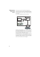
TCP/IP Connection Within a Local Network In this case of use, the receiver and the computer are connected to the same local area network (LAN) and may even be in the same room. Here the communication will NOT take place through the public Internet, but simply within the local network. The connection diagram typically is the following.
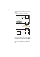
In this case of use, the receiver and the computer are connected to different local networks. Here the communication will necessarily take place through the public Internet. The connection diagram typically is the following.
“Direct” TCP/IP Connection The term “Direct” used here should not be confused with the “Direct IP” connection mode, which is a special case of Internet connection to a static IP address. Here the term “Direct” is used to describe a TCP/IP connection between a receiver and a local computer through a special Ethernet connection, using a crossover cable connected directly between the receiver and the computer. In a crossover cable, the pinout is inverted at one end of the cable.
Bluetooth (see ProFlex 800 Reference Manual, Using Serial Commands Chapter, for more information) $PASHQ,ETH Example of receiver response: $PASHR,ETH,I,ON,00:09:66:00:10:a0,10.20.2.123,DHP=1,ADD=192.168. 0.1,MSK=255.255.255.0,GTW=255.255.255.255,DN1=255.255.255.255,D N2=255.255.255.
10.Enter a different IP address for the computer (e.g. 10.20.2.2). Enter the same subnetwork mask and gateway as those entered above in the receiver through the $PASHS,ETH,PAR command. 11.Click OK twice to close the windows. 12.Connect the crossover cable between the receiver and the computer. 13.Check that the new IP address displayed on the receiver screen is the expected one. 14.Open the web browser on the computer. 15.Type the receiver IP address in the address box.
Managing the Connection Profiles Managing connection profiles can be done directly from the ProFlex Web Server after you have logged in as the administrator. In this context, go to the Configuration tab and use the Advanced Setup menu (Administrator and Users submenus) to make the required changes.
2. Make sure your computer is also ready for a TCP/IP connection. 3. Launch the web browser on your computer. 4. In the Address box of the web browser, type the IP address or host name of the receiver: http:// then press the Enter key. After the connection has successfully been established, the ProFlex Web Server Home tab appears in your web browser. 5. Click on the Status tab. You are then asked to enter the login and password of your connection profile (user or administrator).
First Steps With the Web Server Home Tab The Web Server Home tab appears after you have typed the correct IP address in the Address box of your web browser and pressed the Enter key. In the right-upper corner of the window, you have access to the on-line help (HELP link) and to technical support (SUPPORT link). You can also change the language of the Web Server interface. This will simultaneously change the language of the Help files accessible through the HELP link.
these parameters. For your information, the third column indicates the relevant $PASH commands. Parameter Receiver serial number Owner name Company name Phone Email Designation $PASH Hardware-coded receiver serial number $PASHQ,RID Owner name Name of the company operating the receiver Contact phone number Contact email $PASHS,WEB,OWN $PASHS,WEB,OWN $PASHS,WEB,OWN $PASHS,WEB,OWN (The last four parameters can be changed from the Administrator menu on the Configuration tab.
By column from left to right: Column #1 Mode Position Station ID Age Column #2 Lat Long Height Heading Column #3 HRMS VRMS HDOP VDOP Column #4 GPS GLONASS SBAS GALILEO QZSS Column #5 Battery Receiver operating mode (“Base”, “Rover”, etc.) Type of position solution currently available from the receiver (“No position”, “Autonomous”, “DGPS”, “S-DGPS”, “RTK Fixed”, “RTK Float”) If a base: • 0 to 4095 for a station transmitting ATOM or RTCM3.x corrections • 0 to 1023 for a station transmitting RTCM2.
FTP Push Column #8 Date Time Alarm report Indicates whether the recorded raw data files are uploaded to an external FTP server (“On”) or not (“Off”). Current date (YYYY-MM-DD) Current local or UTC time (hh:mm:ss) according to the setting below. Blank area if no alarm has been detected. “Alarms” displayed if an alarm has been detected in the receiver, followed by the number of raised alarms, between brackets (x). A click on “Alarms” will open the Status-Alarms web page to list this or these alarms.
Angle Unit Latitude Format Used Deg. Min. DD°MM’ SS.SSSSS” N or Sec. DD°MM’ SS.SSSSS” S Longitude Format DDD°MM’ SS.SSSSS” E or DDD°MM’ SS.SSSSS” W Where: • N for North, S for South; E for East, W for West • “D..” for degree digits, “M..” for minute digits, “S..” for second digits When typing in a latitude or longitude, leading and trailing zeroes can be omitted. Degree (°), minute (’) and second (”) symbols can be omitted as well. For example, typing 5 6.45 N is a valid entry for 5° 06.450000’ N.
Setting a Rover 16 How to Start • Open the Web Server’s Configuration tab. The first time you click on this tab, the Web Server will ask you to log in as the administrator. Only the receiver administrator is authorized to access the Configuration tab. You are allowed to change the destination of a receiver (e.g. it is currently a base and you want to change it into a rover).
• Set the GNSS antenna parameters: – Reference Position: Specify the physical point on the rover system for which the receiver will accurately compute RTK positions. The three possible choices are: Antenna L1 phase center, Antenna Reference Point (ARP) or Ground Mark. – Measurement Type: Specify the method that was used when setting up the rover system to measure the height of the GNSS antenna (Vertical or Slant Height).
a virtual antenna model in this field to emulate a GNSS antenna other than the one really used. Choosing a virtual antenna different from the one really used affects the raw data as if they had been collected by the virtual antenna, instead of the real one. When the rover does not have to log raw data, select “Off” in this field as there is no point using a virtual antenna in this case.
Internal Radio ProFlex 800 Internal Radio (UHF radio link) RTK Corrections Radio Base • Unless already done, please follow all the steps described in section General Parameters on page 16 before proceeding with the steps below. • Still on the Rover Setup page, read the content of the Internal Radio Port D pane.
Automatic: The radio will be switched on or off automatically when the rover is respectively turned on or off. Manual: The radio will be powered up only by going through the Rover Setup page, setting the internal radio to “Power On” and clicking on the Configure button (or using the $PASHS,RDP,ON command). – Channel: Select the channel on which you know that the base is transmitting its RTK corrections.
The internal modem should be configured first: • Click on the Connections menu and then on the Bluetooth/ Modem sub-menu. • Set the following parameters in the Internal Modem/Device Settings pane: – Power: Select “On”. Then choose whether the modem should be turned on automatically or manually: Automatic: The modem will be switched on or off automatically when the rover is respectively turned on or off.
– The rover being a client, enter the information (Connect Now, Address, Port, Login, Password) allowing it to connect to the base (the server) from which it is supposed to receive corrections. The login and passwords are required only if the server demands authentication (e.g. SpiderNet). In that case, the message “$GPUID,, will be generated automatically and sent to the server when clicking on Configure.
If you activate the DHCP option, then it’s a good idea to define a hostname for your receiver and declare it to DynDNS (see DynDNS frame at the bottom of the page). DynDNS is a free service that will make sure the dynamic IP address allotted to the receiver by your ISP is always attached to your receiver’s hostname. This requires that you open an account on DynDNS. For more information on this service, see Creating an Account on Dyn.com on page 53.
• At the bottom of the page, in the Differential Port pane, select the Automatic option to let the receiver detect the incoming differential stream automatically. NOTE: Automatic is the recommended choice for the Differential Port setting because in this case, you don’t need to define the ports receiving the two possible differential streams. • Click on the Configure button to let the Web Server load all your new parameters to the receiver.
– Internet Protocol: Choose the Internet protocol (TCP or UDP) allowing the modem to perform an Internet connection. – Access Point: Enter the URL of the mobile communication provider. – Access Point Login: Enter the login of the mobile communication provider. – Password: Enter the password of the mobile communication provider. • Click on the Configure button. • Now please follow all the steps described in section General Parameters on page 16 and then proceed with the steps below.
Select the desired source by simply clicking on the corresponding row. The resulting mount point then appears in the Mount Point field located above the Load Source Table button. – Send NMEA: Check this button when the rover operates in a VRS network so that it can return its position to the network through an NMEA message. Keep it cleared in all other cases. (This option is automatically enabled when you select a mount point for which the NMEA message is requested.
If you activate the DHCP option, then it’s a good idea to define a hostname for your receiver and declare it to DynDNS (see DynDNS frame at the bottom of the page). DynDNS is a free service that will make sure the dynamic IP address allotted to the receiver by your ISP is always attached to your receiver’s hostname. This requires that you open an account on DynDNS. For more information on this service, see Creating an Account on Dyn.com on page 53.
Select the desired source by simply clicking on the corresponding row. The resulting mount point then appears in the Mount Point field located above the Load Source Table button. – Send NMEA: Check this button when the rover operates in a VRS network so that it can return its position to the network through an NMEA message. Keep it cleared in all other cases. (This option is automatically enabled when you select a mount point for which the NMEA message is requested.
• Unless already done, please follow all the steps described in section General Parameters on page 16 before proceeding with the steps below. • Still on the Rover Setup page, in the Serial Port x pane corresponding to the port you want the receiver to use (A, B or F), set the following parameters: – Connection: Choose the name of the corrections receiver device connected to the port. As a general rule, choose “None/Cable” for any external corrections receiver connected to that port.
Rover Acquiring Data Stream From a Base Base Ethernet Data Streaming, port Ix IP address or server name ProFlex 800 (Client) Internet Ethernet RTK Corrections The rover needs to be configured as in Direct IP mode via Ethernet (see Direct IP Via Ethernet on page 22). Rover Operating in Flying RTK Mode • Follow the steps described in section General Parameters on page 16. At the top of the Rover setup page, select Ambiguity Fixing=0 in the Rover pane.
Three categories of output data are possible (NMEA, differential and raw data) but in most rover applications, only the use of NMEA messages makes sense. However, to allow raw data to be recorded in the rover, you should make sure the appropriate messages are set on the U and M ports. Follow the instructions below to program the desired messages: • On the Configuration tab, click on the Data Output menu. • Click on the NMEA Messages submenu.
– To define the output of an NMEA message on a given port, you just need to select the message type from the Message drop-down list, the output port from the Output drop-down list, then enter its output rate, in seconds, in the Rate field, and finally click on the Add button. The new message definition will then appear as a new row in the table on the right. Note that for messages PTT, TTT and XDR, you don’t have to define an output rate, due to the very nature of these messages.
and type “1” in the Rate field. Click on the Add button underneath to validate your entry. The programmed message now appears in the table on the right. – Click on the Configure button located at the bottom of the page • Click on the Connections menu, then on the Serial Ports submenu. • Set each of the ports on which data output will take place. If port B or F is used, make sure the Power ON option (bottom of the page) is active.
Setting a Base How to Start • Open the Web Server’s Configuration tab. The first time you click on this tab, the Web Server will ask you to log in as the administrator. Only the receiver administrator is authorized to access the Configuration tab. You are allowed to change the destination of a receiver (e.g. it is currently a rover and you want to change it into a base). In this case, on opening the Base Setup tab, the Web Server will retain part of the rover settings that could be applied to the base (e.
should be defined accordingly (port E, P or Q + message type), namely the Differential Stream 1 is necessarily associated with “Network 1” (or “NTRIP Server 1”) and Differential Stream 2 with “Network 2” (or “NTRIP Server 2”). Whereas the modem can only serve the “Network 1” or “NTRIP Server 1” connection, the Ethernet port on the other hand can serve both network connections, namely port P for “Network 1”/“NTRIP Server 1” and port Q for “Network 2”/“NTRIP Server 2”.
– Reference Position: Specify the physical point on the base system for which the receiver will generate corrections. The three possible choices are: Antenna L1 phase center, Antenna Reference Point (ARP) or Ground Mark. – Measurement Type: Specify the method that was used when setting up the base system to measure the height of the GNSS antenna (Vertical or Slant Height).
Choosing a virtual antenna different from the one really used affects the raw and differential data as if they had been collected by the virtual antenna, instead of the real one. A virtual antenna is needed at a base when rovers from different GNSS manufacturers cannot operate from that base because of the unknown model of GNSS antenna used by the base. In that case, defining a virtual antenna at the base will solve the problem.
– RTK corrections delivered on port A, B or F – Ethernet data streaming. Defining the Data Generated by a Base Depending on your application, you will have to define different types of data messages as well as the ports through which they will be delivered. Three categories of output data are possible (NMEA, differential and raw data) but only the use of differential and raw data messages makes sense in a base.
process, some message data are sampled, which means that instead of being present in every single message generated by the base, they will in fact be provided every x occurrences of the message. Reconstructing full messages on rover side will however not tolerate data loss in the transmission. The successful use of the “Compact” or “Super Compact” formats therefore demands a very robust data link.
The table below gives average data throughput figures (in bytes/sec) for different GNSS signals and three message types (RTCM-3 given as reference). Protocol/ Scenario ATOM RNX (SCN,4) ATOM RNX (SCN,100) ATOM RNX (SCN,101) RTCM-3 GPS+GLONASS L1/L2 GPS+GLONASS L1 (L1CA only) GPS L1/L2 317 205 193 159* 140* 98* 86* 75* 70* 338 (MT 1004,1012) 214 (MT 1002,1010) 202 (MT 1004) * Worst-case estimates. Real throughputs are often shorter by 4 to 8 bytes.
and then click on the Modify button to save your changes.The table row is updated accordingly. Note that depending on the current selection on this page, the button located underneath the three fields on the left may be either grayed or with a different label (Add or Modify). – Deleting a message definition can be done by simply clicking on the corresponding “trash” sign in the Clear column on the far right. This deletes the table row.
Parameters on page 35. Then proceed with the steps below. • Scroll down the page to display the Transmitter frame. In the Message field, select the type of differential data the base will generate and the radio will transmit (ATOM, RTCM, CMR, CMR+ or DBEN). Following your selection, you will see the detail of the selected data on the right of this field, as defined in Data Output > Differential Messages.
make to these settings will be effective in the radio only after running the last step below. By defining now the settings of the serial port used (A, B or F), you will save time as you won’t need to go through the Connections>Serial Ports submenu to make these settings. • Click on the Configure button to let the Web Server load all your new parameters to the receiver and the radio. You have now reached the end of the configuration phase.
you are using should be able to give you all this information): – Internet Protocol: Choose the Internet protocol (TCP or UDP) allowing the modem to perform an Internet connection. – Access Point: Enter the URL of the mobile communication provider. – Access Point Login: Enter the login of the mobile communication provider. – Password: Enter the password of the mobile communication provider. • Click on the Configure button.
Direct IP Via Ethernet Users ProFlex 800 Internet (Client) IP address or server name Ethernet RTK Corrections • First, click on the Connections> Ethernet submenu. • Set the following Ethernet parameters to allow the receiver to access the network through its Ethernet port: – DHCP: Enabling this option means the local network to which the receiver is connected will automatically allocate a dynamic IP address to the receiver.
• Still on the Base Setup page, make sure the Connection fields in the Serial Port x panes are all set to “None/Cable” • In the Network x pane, choose “Ethernet Direct IP - Port P” in the Connection field. • Because the base is necessarily a client, enter the information (Connect Now, Address, Port) allowing it to connect to the rover (the server) to which it is supposed to deliver its corrections. No Login or Password is needed in this case.
• Set the following parameters in the Internal Modem/Device Settings pane: – Power: Select “On”. Then choose whether the modem should be turned on automatically or manually: Automatic: The modem will be switched on or off automatically when the rover is respectively turned on or off. Manual: The modem will be powered up only by going through the Connections > Bluetooth/Modem page and setting the modem to “Power On” (or using the $PASHS,MDM,ON command). – Automatic Connection: Check this option.
NTRIP caster (the server) to which it is supposed to deliver its corrections. Enable Connect Now to allow the receiver to establish the connection right after you have clicked on Configure. • In the Message field, select the type of differential data the base will deliver (ATOM, RTCM, CMR, CMR+ or DBEN). Following your selection, through a click on the “I” symbol, you will see the detail of the selected data on the right of this field, as defined in Data Output > Differential Messages.
• First, click on the Connections> Ethernet submenu. • Set the following Ethernet parameters to allow the receiver to access the network through its Ethernet port: – DHCP: Enabling this option means the local network to which the receiver is connected will automatically allocate a dynamic IP address to the receiver. If this option is disabled, you need to define the receiver’s static IP address, and give information about the local network (Subnetwork Mask and Gateway).
should choose a mount point from the list of mount points managed by the embedded NTRIP caster. Enable Connect Now to allow the receiver to establish the connection right after you have clicked on Configure. • In the Message field, select the type of differential data the base will deliver (ATOM, RTCM, CMR, CMR+ or DBEN). Following your selection, you will see the detail of the selected data on the right of this field, as defined in Data Output > Differential Messages.
• Make sure the Connection fields in the Network x panes are all set to “None”. • In the Differential Stream x pane, in the Port field, choose the port to which the external device is connected. In the Message field, choose the type of differential message provided through this port (ATOM, RTCM, CMR, CMR+ or DBEN). NOTE: The receiver has been designed to offer two separate and independent differential data outputs. Each one can output a specific type of differential message.
Users ProFlex 800 (Server) Internet Ethernet Ports I1-I9 RTK Corrections Follow the instructions below: • Click on Base Setup > Data Streaming on IP and define the general parameters of the base, as explained in section General Parameters on page 35. Then proceed with the steps below. • Scroll down the page to display the Ethernet Streaming frame. • For each data stream the base should generate, enable the Port Ix option corresponding to the port you want to use.
Creating an Account on Dyn.com Dyn Standard DNS is an update mechanism, offered by Dynamic Network Services, Inc., through which you can make sure the hostname of your ProFlex 800 will always match the dynamic IP address assigned to it by your Internet provider. This however requires that you create an account and choose the function you want to use. Do the following to create an account: • Open a new tab in your web browser. • Type http://dyn.com/dns/ and press ENTER.
• Enter the Hostname of your receiver, as declared when you opened your DynDNS account. • Enter the credentials (Username, Password) you specified when creating your DynDNS account. These will authorize the receiver to access and use the DynDNS service. • Specify the rate (Period), in seconds, at which the receiver should regularly access the DynDNS service to provide its current IP address.
Configuration Memo Entering the settings of a base/rover system is quite straightforward when a radio is used to transmit corrections from the base to the rover. When an IP connection is used, understanding the possible base/rover associations is not so clear because in addition, you have to take account of the server-client requirement inherent in any IP connection.
Arrows show flow of corrections [1] ProFlex 800 Rover ProFlex 800 Base (NTRIP Client) “NTRIP Server” (Client) Ethernet Ethernet [6] NTRIP Caster (Server) [7] Modem ProFlex 800 Base “NTRIP Server” (Client) Modem ProFlex 800 Rover (NTRIP Client) [2] [3] ProFlex 800 Base ProFlex 800 Rover (Direct IP Client) Data Streaming on IP (Direct IP Client) [8] Ethernet Iz, server Iy, server Ix, client ProFlex 800 Base (Direct IP Client) ProFlex 800 Rover Modem Ethernet [9] Ethernet [9] [4] ProF
Index Symbols $GPUID 22, 23 $PASH commands 11 A Access point 21, 25, 44, 47 Adaptor cable 3 Address box 11 Administrator profile 2, 9, 12 ADSL modem 5 ADVNULLANTENNA 37 Age of corrections 13 Airlink speed 20 Ambiguity fixing 16, 30 Angle units 14 Antenna (virtual) 17, 36 Antenna height 17, 36 Antenna measurement type 17, 36 Antenna radius 17, 36 ARF7474 29, 50, 51 ARP 17 ASH-661 (ASH111661) 17, 36 Associations (base/rover) 55 ATOM 32 ATOM, standard, compact, super-compact 38 Automatic (detection of port
LAN 4, 5 Latitude 13 Latitude (entering a latitude, possible formats) 14 Load Source Table 25, 27 Local Area Connection 7 Local settings 9 Longitude 13 Longitude (entering a longitude, possible formats) 14 M MAC Address 23, 27, 45, 49 MAG111406 17, 36 Manual (modem DC power) 21, 24, 43, 47 Manual (radio DC power) 20 Memory 13 MES 32 Message type 52 Modem Direct IP - Port E 21, 44 Modem power status 13 Mount point 49 Moving base 16 Moving position 35 N NAV 32 NMEA messages 31 NTRIP caster 25, 27 NTRIP cli
W Web browser 1 59
Web Server Getting Started Guide Contact Information: SPECTRA PRECISION DIVISION 10355 Westmoor Drive, Suite #100 Westminster, CO 80021, USA www.spectraprecision.com Rue Thomas Edison ZAC de la Fleuriaye, BP 60433 44474 Carquefou Cedex, FRANCE © 2012-2013 Trimble Navigation Limited. All rights reserved. Spectra Precision is a Division of Trimble Navigation Limited. Spectra Precision and the Spectra Precision logo are trademarks of Trimble Navigation Limited or its subsidiaries.