ProMark 800 ™ Getting Started Guide
Copyright Notice All product and brand names mentioned in this publication are trademarks of their respective holders. and found to comply with the regulations regarding exposure to RF Energy. SAR was measured with the unit (GSM Module) transmitting at its maximum certified RF power. Often, however, during normal operation the unit (GSM Module) will transmit much less than maximum power. Transmit power is controlled automatically and, in general is reduced as you get closer to a cellular base station.
Introduction ........................................................................................1 What is ProMark 800?............................................................1 Scope of this Guide ...............................................................1 System Components Overview..............................................................2 Basic Supply.........................................................................2 Standard Accessories ............................................
English
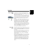
What is ProMark 800? Congratulations! You have just acquired the latest multifrequency, multi-constellation ProMark 800 GNSS Surveying System from Spectra Precision! GNSS has revolutionized control surveys, topographic data collection and construction surveying. Purchasing the right tools for a professional job is essential in today's competitive business environment. Learning to put these tools to work quickly and efficiently will be the focus of the present manual.
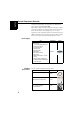
System Components Overview English The tables below provide an overview of the different key items composing the ProMark 800. Depending on your purchase and based on the type of survey you wish to perform, you may only have some of the listed items. Please refer to the packing list for an accurate description of the equipment that has been delivered to you. NOTE: Spectra Precision reserves the right to make changes to the list of items provided below without prior notice.
Part Number Picture English Item AC/DC Power Supply Kit (includes external AC adapter, battery charger and 802064 cable extension for powering ProMark 800 directly from the AC adapter) Communication Modules and Associated Antennas Vertical Antenna Extension 103717 HI Measurement Tool 111146-1 Field bag 206490-ASH Item Part Number 87330-00: ADL Vantage Kit, 430-470 MHz, 4 W 87330-20: Accessory kit, 430-450 MHz 87330-10: Accessory kit, 450-470 MHz Each accessory kit includes a unity-gain ADL Vant
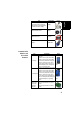
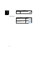
Item Part Number Picture English Quad-band GSM 111397 antenna Base Accessories Item 4 Part Number Power cable kit 802143 ADL Vantage (Pro) to ProMark 800 cable (PacCrest ref.
English Equipment Description & Basic Functions Front Panel View Display Screen Log Button Power Button Scroll Button Power LED Indicators & Controls Power button To turn on the ProMark 800, hold the Power button pressed until the power LED lights up. To turn off the ProMark 800, hold the Power button pressed until the “Ashtech” screen is displayed. Then release the button and wait until the ProMark 800 shuts down. Power LED This indicator is on when the ProMark 800 is on, and off when it is off.
English After a few seconds of inactivity (i.e. Scroll button idle), screen luminosity turns from high to low level. Scroll button Press this button shortly to scroll through the different pages of information viewed on the screen. If an alarm is reported on the display screen, a short press on the Scroll button will acknowledge the alarm. The Scroll button will recover its display scrolling function only after all the alarms have been acknowledged this way.
Battery Model & Battery Compartment English Battery, Connectors & Module The battery used in the ProMark 800 is a 7.4-V DC - 4600 mAh rechargeable battery. It is a standard model used in many camcorders. The battery is housed in a battery compartment accessible from underneath the ProMark 800. The compartment door can be removed using a coin to release the two quarter-turn screws.
USB Port English A nine-contact female connector (Fischer type). Depending on how it is configured, the USB port can be used in two different ways: 1. For a USB host such as a mass storage device. In this case, you should use the special adaptor cable provided (P/N 702103) to attach the USB key to the ProMark 800. This configuration can be used to log raw data on the USB key or upgrade the ProMark 800 firmware from the files stored on the key. 2.
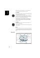
The diagram below gives the dimensional parameters of the ProMark 800 antenna required for the system to determine the true height of the antenna from the measured value obtained using one of the standard height measurement methods, i.e. slant or vertical. Antenna Radius = 98 mm Height Mark 104.0 mm 100.1 mm L1 L2 SHMP Offset =40 mm The height mark allows you to hook the measure tape onto it so you can unroll the tape down to the survey mark and read the slant height measurement directly on the tape.
Display Screens English If you press the Scroll button several times, you will see the following displays successively. Power-On Screen When you power on the receiver, the Ashtech logo appears on the screen. It is displayed until the receiver has completed its auto-test (this takes about 30 seconds). Then the General Status screen is displayed. General Status Screen An example of General Status screen is shown below.
• : Data link icon [5]. This icon is displayed only when corrections are received. • Age of corrections [6], in seconds. This value is displayed when corrections are received and only after base station information has been received (Position status is at least “DGPS”). • Raw data logging icon [7]: Data recording through front panel Log button: – Blinking: Raw data logging in progress – Fixed: No raw data logging in progress. ATL data recording for advanced diagnosis.
English • GSM module (modem) status [12]. This may be one of the following icons: Icon Blank Definition Modem turned off. Blinking icon: Modem turned on but not initialized yet. Indicates signal strength at modem antenna input. Fixed icon: Modem turned on and initialized (ready for a connection). Indicates signal strength received at modem antenna input. The higher the number of bars, the better the signal. This icon will show four dots at the bottom when the input signal is zero.
About the “*” symbol: • It can only appear at the end of the first or third line. • Where placed, it indicates that this storage medium is used for data logging. What if there is no USB mass storage device connected to the receiver? • Parameters relevant to the USB key size and space used and available are void (three dots displayed instead). • Number of files is forced to “0”.
English depending on whether or not a projection is defined in the local coordinate system used), If the receiver is a rover, the displayed position will be the last computed position. The coordinates will be local (“LOC”) only if the rover receives specific RTCM messages from the base describing the local system used by the base. If the receiver is a base, the displayed coordinates are set ones (not computed ones) representing the WGS84 or local reference position assigned to the base.
ATL Recording Screen Pressing the Scroll button from the Position Computation screen –or from the Radio Settings screen if there is a radio used– will take you to the ATL Recording screen, which looks like one of the following, depending on whether a USB key is connected to the receiver (below, right) or not (below, left).
English Memory Management Screen From the ATL Recording screen, press the Scroll button to access the Memory Management screen. The flowchart below summarizes the different tasks you can perform at this point in the management of the receiver memory. ATL Recording Screen Scroll button Clean up internal memory? No Yes No Delete all G-files? Yes Delete all files? No Format memory? Yes Yes No Yes Confirm? In progress...
Make sure the battery is fully charged for each ProMark 800 you will be using in the field. Follow the instructions below to charge a battery. Removing the Battery from the ProMark 800 Unless the battery has already been taken out, do the following: • Put the ProMark 800 upside down. • Remove the battery door, accessible from underneath the ProMark 800, by loosening the two quarter-turn screws (see picture) using a coin.
English then push the battery against the plate and slide it forward [2] until it locks into place. 1 2 [1] MED HI MAX [3] [4] [5] [6] MED HI MAX MED HI MAX MED HI MAX Inserting the Battery in the ProMark 800 18 [2] • Plug the adapter into an AC outlet. Battery charging starts immediately. For a low battery that’s being charged, you will first see the three LEDs switch on and off, one after the other, followed by a short period of time when none of the LEDs is on (see [3]).
• You will need a tripod and a tribrach (not provided) to install the base. The provided antenna extension pole fitted with a 5/8” male adapter is also required in this configuration. • For a long-range radio link, i.e. more than 1 mile or 1.6 km, for which the radio antenna should be placed as high as possible, it is good practice to install the antenna on top of an antenna pole secured on a tripod (neither of these items is provided). • To power the radio, you need an external 9-16 V DC power source.
RTK Rover Setup English Prerequisites • Use a range pole fitted with a 5/8” male adaptor at the upper end (not provided). • If a radio link is used with the base, your rover should normally have been fitted with the radio module that matches the reception band covered by the radio transmitter used at the base. • If a GPRS connection is used, your rover should normally have been fitted with the SIM card that will allow it to perform a network connection.
Starting/Stopping Raw Data Logging You simply need to use the Log button to start and stop raw data logging. Later, you will however need to do the following manually: 1. Downloading phase (if appropriate, rename the raw data files collected on each site). 2. Post-processing phase: Manually correct all computed elevations for the antenna height. By default, raw data is logged to the receiver’s internal memory.
English • If you do not press any button within the next 10 seconds, the download procedure will be canceled automatically and the screen will come back to the previous display. Using the USB Cable Provided • Connect the USB cable provided (P/N 702103) between the office computer and the receiver’s USB port. The receiver is then seen as a USB device from the office computer • Using Windows Explorer on your office computer, browse the receiver’s internal memory for the raw data files.
A K AC/DC power supply kit 3 Alarm status 11 Alarms 6 Antenna characteristics 9 Antenna extension 3 AUTO 10 Key combinations 9 Kinematic 1 B Backlight 6 BASE 10 Battery (external) 19 Battery (insert) 18 Battery (remove) 17 Battery charger 3 Battery icon 11 Battery model 7 BLADE 1 Bluetooth 8 Bluetooth identifier 13 Bluetooth status 12 Buzzer 6 C Charging battery 17 D Data link icon 11 Data transfer screen 16, 21 DC power input 7 Device cable (USB) 2, 21 Display screen 5 F Factory settings 9 FAST Surv
U English USB port 8 USB status 12
ProMark™ 800 Getting Started Guide Contact Information: SPECTRA PRECISION DIVISION 10355 Westmoor Drive, Suite #100 Westminster, CO 80021, USA www.spectraprecision.com Rue Thomas Edison ZAC de la Fleuriaye, BP 60433 44474 Carquefou Cedex, FRANCE ©2011-2013 Trimble Navigation Limited. All rights reserved. Spectra Precision is a Division of Trimble Navigation Limited. Spectra Precision and the Spectra Precision logo are trademarks of Trimble Navigation Limited or its subsidiaries.