SURVEY PRO ® for Windows CE GPS User’s Manual 2002 Tripod Data Systems, Inc.
GPS User’s Manual TRIPOD DATA SYSTEMS SOFTWARE LICENSE AGREEMENT IMPORTANT: BY OPENING THE SEALED MEDIA PACKAGE, YOU ARE AGREEING TO BE BOUND BY THE TERMS AND CONDITIONS OF THE LICENSE AGREEMENT AND LIMITATIONS OF LIABILITY ("Agreement"). THIS AGREEMENT CONSTITUTES THE COMPLETE AGREEMENT BETWEEN YOU AND TRIPOD DATA SYSTEMS, INC. ("Licensor").
Table of Contents GPS Coordinates................................................................................... 2 Datums ....................................................................................... 2 Horizontal Datums....................................................................................4 Vertical Datums .........................................................................................6 Coordinate Systems .................................................................
GPS User’s Manual Bluetooth Error Messages ...................................................................... 61 Projection Utilities.............................................................................. 63 Projection Calculator .............................................................. 63 Scale Factor Calculator ........................................................................... 63 Convergence Calculator .........................................................................
Introduction This book is divided into two parts. The first part is the user’s manual. The second part is the reference manual. The users manual includes a brief explanation of the basic concepts of GPS coordinate systems and GPS measurements. The following sections cover step-by-step instructions on how to use Survey Pro GPS for RTK and post processing data collection. At the end of the user's manual are some tutorial jobs you can do to illustrate the instructions in the book.
GPS Coordinates To represent positions in space you need two things. First, you need a datum to define an origin, an orientation, and a scale. Second, you need a coordinate system to specify the locations in the datum. GPS positions are in a global geocentric datum, using latitude and longitude angles to specify location. Most engineering and surveying jobs require positions in a 2D Cartesian coordinate system.
GPS Coordinates Geocentric datums such as WGS84 use a rotational ellipsoid to model the shape of the earth. The WGS84 ellipsoid was based on and is virtually identical to the Geodetic Reference System of 1980 (GRS80) ellipsoid. The ellipsoid origin is at the earth’s center of mass. Its minor axis corresponds with the earth’s rotation axis and its major axis corresponds to the mean equatorial plane. WGS84 Geodetic v.
GPS User’s Manual Below is a description of some common horizontal and vertical datums used by Survey Pro. Horizontal Datums • NAD27 The North American Datum of 1927 (NAD27) horizontal datum was established in the early part of the twentieth century to define a horizontal coordinate system in North America. The datum originated at a central point, Meades Ranch in Kansas. From there, conventional triangulation and trilateration networks radiated outward to establish new monuments in the system.
GPS Coordinates (ITRF). Because the earth’s center of mass and spin axis drift over time, you will often see the WGS84 datum followed by brackets (1996.0). The date in the brackets indicates the epoch defining the datum. This is all quite confusing. Fortunately, for most RTK GPS applications, you do not need to worry about these WGS84 differences. The significant part of the datum difference is a shift, and you correct this when you specify the GPS base position.
GPS User’s Manual • Custom Datum Transformations Most North American and international datums are pre programmed into the Survey Pro coordinate system database. If you require a datum not programmed into the database, you can use the Projection Key In Wizard to create a custom Molodensky or similarity datum transformation. Vertical Datums GPS satellites orbit the Earth’s center of mass, while objects on the surface of the planet are affected by the force of the local gravity field.
GPS Coordinates • NGVD29 The first continental height datum in the United States was the National Geodetic Vertical Datum of 1929 (NGVD29). According to the technology of the day, this datum was based on normal gravity, that is, the gravity field at the instrument when it was leveled. Points along the coast were chosen and their elevation above sea level was determined from a network of tide gauges. Spirit level networks were then run across the country and closed on the opposite coast.
GPS User’s Manual Coordinate Systems A coordinate system is a way to describe positions in a datum. Coordinate systems range from simple Cartesian (y,x) or (N,E) positions on a flat plane to complex geodetic latitudes and longitudes on a reference ellipsoid. Below is a description of some coordinate systems common in surveying: • Northing, Easting, Elevation Survey projects usually use simple plane coordinates.
GPS Coordinates • ECEF XYZ Geodetic coordinates are some times given in the Earth Centered Earth Fixed (ECEF) Cartesian coordinate system. This coordinate system has its origin at the Earth’s center of mass, the primary (Z) axis is the earth’s spin axis; the secondary (X) axis is the intersection of the equatorial plane and the mean meridian of Greenwich; the tertiary (Y) axis is orthogonal in a right handed system.
GPS User’s Manual Horizontal Coordinate Systems Survey projects use horizontal coordinates on either a local plane or a map projection. For small projects, you can assume a simple flat earth plane and calculate coordinates directly with measured distances. Use TDS localization mode for this procedure. For large projects, a mapping plane is used to accurately represent the curved surface of the earth on a flat plane and conventionally measured distances need to be scaled to the mapping plane grid.
GPS Coordinates • Area A map projection is equi-areal when it correctly plots areas over the entire map. That is, all mapped areas have the same proportional relationship to the areas on the Earth that they represent. Common Conformal Map Projections in Surveying • Transverse Mercator The Transverse Mercator (TM) projection results from projecting the ellipsoid onto a cylinder tangent to a central meridian.
GPS User’s Manual Lambert projections are used for about half of the State Plane Coordinate System zones in the USA. • Stereographic The Stereographic projection results from projecting an ellipsoid onto a plane. Directions are true from the center point and distortions in scale, area and shape increase uniformly away from the central point. The stereographic projection is azimuthal.
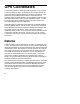
GPS Coordinates K=1.0 K>1.0 • K=1.0 K<1.0 K=0.9996 K>1.0 Distance on Ellipsoid so id Distance on Map El li p Mapping Plane Central Meridian Fig. 3: Transverse Mercator Mapping Plane A side view of the cylinder shows the effect of scale distortion. Universal Transverse Mercator Projection The scale factor at the central meridian (CM) is 0.9996. The scale factor is 1.0 approximately 170-km east and west of the CM. The scale factor is less than one between the CM and the point of tangency.
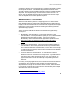
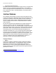
GPS User’s Manual Ellipsoid Scale Factor This scale factor accounts for the height of the ground above the reference surface (the ellipsoid). This scale factor is defined geometrically: Consider the following diagram: Distance on Ground Ellipsoid Height, h distground/(R+h) = distelip/R Distance on Ellipsoid distelip/distground = R/(R+h) kelip = R/ (R+h) Radius of Ellipsoid, R a R= (1 − e sin φ ) 2 R+h 2 1 2 Fig.
GPS Coordinates Geoid Models in TDS Software Survey Pro has several geoid models in the coordinate system database. All of the geoid models use data files in geoid grid file (*.GGF) format. Note: To use a geoid model, geoid data files (*.GGF) must be in the Geodata directory. • Users in the U.S.A., Mexico, and the Caribbean can use either the NGS Geoid96 or the NGS Geoid99 models. This coverage includes the continental United States, Alaska, Hawaii, Mexico, and the Caribbean.
GPS User’s Manual Survey Pro Coordinate System Database Survey Pro uses a Coordinate System Database file (*.CSD) to store the map projection and datum transformation parameters for many different coordinate systems around the world. Also, horizontal and vertical localization adjustments are stored as site records in the database. Below is a list of the terminology used to describe the different records in the coordinate system database. • Zone: Is the basic record type.
GPS Measurements This section gives a brief explanation of GPS measurements. First, a discussion of the basic theory of differential positioning will familiarize you with different solution types and their expected precision. Next, step-by-step instructions will describe how to configure Survey Pro with GPS receivers to perform either Real Time Kinematic (RTK) GPS or data collection for post processing differential GPS.
GPS User’s Manual Differential Solutions: Types and Quality Code Differential Code differential solutions use the Coarse Acquisition (C/A) navigation code transmitted on the GPS carrier wave. Because the wavelength of the code segment is long (300m), code differential is the least precise differential solution. Accuracies of 1-10 meters are possible with DGPS using C/A code differential positioning.
GPS Measurements Differential GPS with Survey Pro DGPS requires raw data measured from separate receivers to be combined into a single range difference. For Real Time Kinematic (RTK) data collection, the raw data can be broadcast using a radio link or cell phones and the differential solution is solved in real time. For Post Processing data collection, the raw data is collected in each receiver’s internal memory and downloaded to a PC.
GPS User’s Manual RTK Settings If you are using Survey Pro for RTK, or RTK and post processing simultaneous data collection, the following cards of the Job, Settings screen contain settings specific to RTK: • Measure Mode: is where you select the receiver dynamic for point occupations and the type of GPS raw data to store for each point. You can also specify measurement acceptance criteria. For more information see the Reference Manual.
RTK Data Collection RTK data collection uses differential GPS corrections broadcast by a base receiver to solve for coordinates at a rover receiver in real time. This section describes how to use Survey Pro for RTK GPS data collection.
GPS User’s Manual Projection Mode Summary Horizontal Ground - TDS Localization • Local coordinates are at ground level, based on the project height. • Distances shot with EDM are at ground scale, so are 1:1 with coordinates solved by the projection. • Default map projection and datum are automatically initialized with RTK base setup. Mapping Plane • Local coordinates are on a conformal map projection grid.
RTK Data Collection Note: If you are using Ground- TDS Localization for your horizontal projection mode, and you want to use a geoid, you only need to select the geoid model once. Survey Pro remembers the geoid model you last used and will automatically assign this geoid in a new job's Localization map projection zone. You can go directly to Receiver Setup after opening a job.
GPS User’s Manual Mapping Plane Setup Use the Mapping Plane Setup screen to either select a map projection zone from one of the zone groups, or select a localized map projection site from the database. This screen is also used to open the Projection Key In Setup wizard where you can key in the parameters of a custom map projection and datum. 1. Tap … on the Horizontal card of the Projection screen to open the Mapping Plane Setup screen. 2.
RTK Data Collection • Use the Key In Parameters button to open the Projection Key In Setup screen where you can configure a custom map projection and datum. Projection Key In Setup Use the Projection Key In Setup screen to create a custom map projection and a custom datum transformation to use as the selected mapping plane zone: 1. Tap Select Zone… on the Horizontal card of the Projection screen to open the Mapping Plane Setup screen. 2.
GPS User’s Manual • • North\East Grid. Select this choice to have coordinates increase positive in the north and east directions. South\West Grid. Select this choice to have coordinates increase positive in the south and west directions. Note: The geodetic calculation engine and the Survey Pro coordinate geometry engine are separate components. While the geodetic engine can properly handle southwest grid systems, Survey Pro can only operate on a northeast grid system.
RTK Data Collection Note: Note the sign of the datum shift and rotation parameters. Some datum transformations are given in terms of local datum to WGS84. Survey Pro always assumes datum transformation parameters are WGS84 to local. You might need to reverse the sign of the datum parameters you have to use them in Survey Pro. 14. Tap . If you are using a Custom Molodensky datum, the next screen will be the final screen where you can the record. 15.
GPS User’s Manual Remote Elevation If you set your base on a known benchmark, you can begin collecting data right away. However, if your base station is on a new point, then you should calculate the elevation of the base and create or update a vertical site before collecting new data. You can use the Remote Elevation routine to occupy a vertical benchmark with the rover.
RTK Data Collection 3. If your benchmark is a point in the job file, use the button to select the point, or enter the point number in the Select Point field. 4. Occupy the benchmark with the rover and tap to access the Occupy Control Point screen and begin measurements to the point. 5. When you are satisfied with the measurement, tap . You will return to the Remote Elevation screen and the base station’s calculated new elevation is displayed.
GPS User’s Manual Receiver Setup General Hardware Configuration 7. Connect the power cable or insert the internal battery into the GPS receiver. 8. Connect the antenna cable. + - Power Serial Serial GPS Antenna Battery Receiver 9. Plug the data collector serial cable into a receiver comm. port. 10. If your receiver does not have an internal radio, plug the radio serial cable into a receiver comm. port. An external radio may need its own power supply. If the radio comm.
RTK Data Collection 16. Communications is now set. Tap Format for RTK Corrections 17. Select your Format for RTK Corrections from one of the choices in the combo box. Receiver to Radio Communications 18. Select the type of radio modem you are using. 19. Make sure the baud; parity; and port is correct for the radio. On the Base/Rover Radio card, verify the settings. If settings are not correct, tap and set the correct values. 20.
GPS User’s Manual Survey menu, the correct COM port and settings will be set automatically. Base Station Receiver Setup Use the Base Setup screen to configure a GPS receiver to be an RTK base station and to set the base reference position in Survey Pro. 1. Tap ! " on the Survey menu to open the Current GPS Base screen where information about the current setup is displayed. Tap "… to start the Base Setup wizard. Pick the Base Point 2.
RTK Data Collection base setup. You then SET this reference position in the GPS receiver and configure the base coordinate in Survey Pro. Note: It is strongly recommended that you use only one autonomous GPS base position in a job. If you must use multiple autonomous setups in a single job, you will be prompted to setup and select a separate site record for each setup group. 4. Tap . Set the Base The final step of the Base Setup wizard will depend on the base point chosen.
GPS User’s Manual SET Base at Known Geodetic Coordinate 5. Tap $ to configure the base receiver with this position and begin broadcasting RTK corrections over the radio link. Note: If you have post processing data collection turned on, the receiver will now open a file (with the next available default name), start recording GPS raw data, and enter the station and antenna information for this setup. 6. When done, you will return to the Current GPS Base screen where the base station details are displayed. 7.
RTK Data Collection Rover Receiver Setup Use the Rover Setup screen to configure a GPS receiver to be an RTK rover. 1. Go to Rover Setup from the Survey menu. Rover setup procedure depends on how the base was set. If the base was set with this data collector, the base reference position is already known in Survey Pro and you can simply SET the rover to start your survey.
GPS User’s Manual c. Note: If you have post processing data collection turned on, the receiver will now open a file (with the next available default name), start recording GPS raw data, and enter the antenna information for this setup. d. Once the base station location is received over the radio link, you are prompted to set the base reference position is Survey Pro. If the base coordinate already exists in your job file, then that point is chosen by Survey Pro as the base point.
RTK Data Collection least squares solution using the control points. These parameters are added to the zone record (selected map plane zone or default Localization zone) to create a zone based site record. Vertical Localizations, with or without a geoid model, uses the same field procedure. Starting from an autonomous GPS base setup, you measure GPS positions on control points with know local elevations. The vertical adjustment parameters are calculated from the control points.
GPS User’s Manual ¾ ¾ ¾ ¾ ¾ Take GPS measurements to a minimum of two horizontal control points, and either one vertical control point (to calculate shift for geoid model) or three vertical control points (to calculate an inclined plane). Go to Projection from the Survey menu. Tap ' ( ) Select the points to use for horizontal and vertical control and tap & . Verify solution residual or misclosure quality. Tap & to review the parameters and tap " to finish setup.
RTK Data Collection Note: If you select a point from the job’s control file, you will be prompted to make a local copy of the point. Control point collection will add a geodetic coordinate to the point record and points in the job’s control file cannot be modified. Note: If Store GPS Raw Data on the Measure Mode card of the Job, Settings screen is set to EP + Rx Raw (or + OBN for Ashtech users), when you begin a point occupation the control point name is checked as a valid site ID for the receiver.
GPS User’s Manual 8. Tap ' ( to open the Solve Localization wizard. Note: If you are using localization for the vertical transform mode, then the next screen will look like the illustration below. If you are using ellipsoid heights, then the vertical column will be missing. 9. In the list box, control points collected will be identified with an H and/or V. Points marked H will be used to solve horizontal localization. Points marked with a V will be used to solve vertical localization.
RTK Data Collection • Unique: the solution was calculated using less than the minimum number of control points (1 horizontal or 2 vertical). In this case, there is no least squares solution so the numbers in the N Err, E Err, and/or V Err columns are misclosures calculated from the control points not used in the solution. • LSQ: the solution was calculated with at least the minimum number of control points (2+ horizontal and/or 3+ vertical).
GPS User’s Manual Manual Entry of Parameters Manual entry of parameters is used when you already know the appropriate horizontal and vertical localization parameters for a site. Use manual entry of parameters to key in the site parameters and set it as the current projection record. If you already know the scale, rotation, translation, and origin for a horizontal site, or if you know the slope, shift and origin of a vertical site, you can manually set the localization parameters. 1.
RTK Data Collection Localization Parameters Explained Before you accept a localization solution, you should evaluate the parameters and the quality of the solution. This section describes the meaning and the expected values for the six horizontal and five vertical localization parameters. Guidelines for the quality and geometry of control points plus the solution redundancy and residuals are also described.
GPS User’s Manual Mapping Plane Mode: Scale: is the scale difference between the intermediate mapping plane using the autonomous GPS position and the actual mapping plane control coordinates. Scale should be very close to 1.0. A value of 1.0 corresponds to grid distances on the selected conformal mapping plane. A scale value significantly greater or smaller than 1.0 may indicate problems with the control point accuracy and/or the control measurement precision.
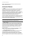
RTK Data Collection Normal to Geoid Normal to Ellipsoid Deflection (a,b) Separation rface Geoid Su Surface Ellipsoid Fig. 9: Vertical Localization Three control points calculate a plane to model the deflection and shift between the geoid and ellipsoid surface. Vertical Calibration and Geoid Modeling If you do not use a geoid model, vertical localization will solve for slope and separation using the measured heights and the control elevations.
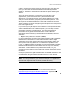
GPS User’s Manual • Geometry of control points: the control points should be distributed evenly surrounding the survey area. Fig. 10: Good Control Point Geometry Three control points surround the project area. Fig. 11: Poor Control Point Geometry Three control points in one corner of the project area. Also, for vertical localization, the three control points are close to co-linear.
RTK Data Collection Ground - TDS Localization Explained: When the horizontal projection mode is Ground - TDS Localization, a default map projection is automatically set up to produce ground coordinates at the base station height. The TDS Localization map projection is an oblique stereographic map projection with the following parameters: o o o Origin is at the initial base station location False northing and false easting of 100000.
GPS User’s Manual • When you collect geodetic measurements, each new point is assigned the set up group of the current base station. • When you set the base on an existing point with geodetic coordinates, the point’s existing set up group is used as the new base station set up group. • When you set the base on a point with existing plane coordinates and compute geodetic coordinates using the ‘Move Base’ algorithm, the existing base station set up group is used as the new base station set up group.
RTK Data Collection • Delta N and E are the translations between the desired local start coordinate and the origin of the TDS Localization map projection (100000, 100000) m. 5. Tap " . You are now ready to start data collection. Localization Calculator Note: The Localization calculator is used to provide the field procedure for a workflow supported in Survey Pro versions prior to 3.5.
GPS User’s Manual 6. Examine the results. The Rotation is the negative of meridian convergence between the central meridian of the selected map projection zone and the base point. 7. If you set your base up on a known point, then the base station coordinates are already entered into the Base Station Local Coordinate fields. Tap & to calculate the localization parameters. Tap " to finish setup and return to the Projection screen. 8.
RTK Data Collection RTK Data Collection Once your horizontal and vertical projections are solved, you are ready to collect data. The different measure mode settings and data collection options are described below. Measure Mode 1. Go to Data Collection from the Survey menu. Tap top of the screen. at the 2. Select the receiver dynamics. ¾ ¾ Static on occupy will set the receiver to ‘static’ mode for point occupations.
GPS User’s Manual Note: Raw data types + Rx Raw (and/or + OBN for Ashtech users) are only available when Receiver Dynamics is set to Static on occupy. Note: All receivers need to be in static mode to record Rx. Raw, and some receivers always record Rx Raw when in static mode. If the combination of settings you select is not compatible for your receiver, you will be prompted to change the settings.. 4. Select the Accept filter. ¾ Fixed RTK only will reject all positions that are not fixed.
RTK Data Collection Data Collection Methods Data Point Use this method if you want to occupy points one at a time. 1. Go to Data Collection from the Survey menu. 2. Enter a point name in the Point field. If this point already exists, you will be prompted to overwrite or choose the next available point. Note: If you have Store GPS Raw Data set to + Rx Raw (or + OBN for Ashtech users), your point name must be a valid Site Id for the receiver model.
GPS User’s Manual Offset Point Use this method if you cannot occupy a point directly, but you can occupy a location close by and provide an azimuth and distance to the point. 1. Go to Data Collection from the Survey menu. 2. Enter a point name in the Point field. If this point already exists, you will be prompted to overwrite or choose the next available point. 3. Enter a Description. 4. Tap to open the Offset Shots screen.
RTK Data Collection ¾ ¾ 8. Tap Occupying a point on line with the reference point and the offset point. After you occupy the reference point, tap , % and then occupy a point on line with the reference point and the offset point. When you are done occupying the on line point, you will be prompted for the direction to your offset point. Entering a value by hand. to store the point. 9. Store any number of additional offset points from this GPS reference point.
GPS User’s Manual 4. Tap . On the Feature Collection screen, select a Method. An explanation of the selected method is displayed at the bottom of the screen. See the reference manual for more information. 5. If you select a continuous method, you must specify an appropriate Interval. 6. Tap to begin measurements. The Occupy Data Point screen displays the local coordinate. 7. When you are ready to begin continuous collection, tap " . 8.
RTK Data Collection RTK Stake Out Stake out with GPS is very similar to stake out with conventional instruments. See the user’s manual for details on the different staking procedures. Below is a description of the two special features of stakeout with GPS. o & / & "+ 1. When you first start any GPS staking screen, measurements are started in the GPS receiver in dynamic (moving) mode.
GPS User’s Manual Bluetooth Communication Survey Pro can communicate using a wireless Bluetooth connection. Bluetooth technology uses a short-range radio connection between a Bluetooth-enabled data collector and a Bluetooth-enabled receiver as an alternative to a cable serial port connection. This section explains how to configure Survey Pro to take advantage of Bluetooth and discusses its limitations. Configuring the Bluetooth Settings 1.
RTK Data Collection 3. Open the Microsoft® Bluetooth Device Management applet. This is typically accessed from the Windows® CE.NET Control Panel. It can also be accessed while running Survey Pro in either of the following two ways: Method 1: • While running Survey Pro, escape to the Windows® CE.NET operating system by pressing Ctrl , [ESC]. • Tap | Bluetooth | % and then double-tap the icon.
GPS User’s Manual 8. After returning to the Receiver Communication screen, tap and the new trusted device will be displayed. 9. Tap to continue. Bluetooth Limitations Bluetooth can be thought of as a short-range radio link. As with any radio link of this type, communications can be interrupted by a number of reasons, including, but not limited to: • The operating range between the devices is exceeded. (The Bluetooth range is limited to approximately 10 meters.
RTK Data Collection Recovering from Signal Loss If Bluetooth communications failure occurs and the software is not able to recover, you may need to uncheck and then re-check the ; Enable Bluetooth checkbox from the Bluetooth Device Management screen. This screen is accessed from either of the methods described in Step 3, under Configuring the Bluetooth Settings, above.
Projection Utilities Projection Calculator You can use the Projection Calculator to calculate combined scale factor for scaling conventional distance measurements to the mapping plane. You can also use the Projection Calculator to calculate meridian convergence for reducing geodetic azimuths (like a sun shot) to grid bearings. Scale Factor Calculator 1. Go to Projection Calculator from the Survey menu. 2. Choose a point on the mapping plane for scale computation in the Select Point control.
GPS User’s Manual Convergence Calculator 1. Go to Projection Calculator from the Survey menu. 2. Choose a point on the mapping plane for convergence computation in the Select Point control. Tap &. 3. The convergence and rotation are calculated. The convergence is displayed in the Geodetic N to Grid N box. The rotation is displayed in the Grid N to Geodetic N box. 4. Tap " when you are done. Both numbers are saved in the Past Results list so you can use them in other calculations.
Projection Utilities 4. Tap % & . You will be warned that coordinates will be changed. If you are sure you are ready to proceed, tap . 5. The final page displays the results. The Results box displays the number of points adjusted. If some points were not adjusted, a list of these points and an explanation why they were not adjusted is displayed.
GPS User’s Manual 5b. Tap & to generate new GPS coordinates based on the plane coordinates. This action will change point records and you will be prompted to ensure you are ready to proceed. 6. The final screen displays the results. The Results box displays the number of points checked or adjusted. If you checked points, the Results box also displays the horizontal and/or vertical error and if any points were not checked.
Projection Utilities Note: If your projection is a localized site, then any errors in the localization solution will propagate through to the new coordinate system, possibly degrading precision of the conventionally measured coordinates. 1. Select all job file points, and select to adjust H and V. 2. Tap % and tap 3 to verify the accuracy of the geodetic to local transformation. Rectify any problem coordinates. 3.
Managing GPS Coordinates with TDS Survey Pro for Windows CE uses a binary file with the extension *.job. A .JOB file point record will contain a point name, plane location (N, E, Z), and a description. It may also contain geodetic coordinates for points calculated, imported, or measured with GPS, as well as poly lines, alignments, layers, attributes, and automatic line work structures. This section describes different ways to manipulate geodetic coordinates with both Survey Pro and Survey Link.
Managing GPS Coordinates % • GPS Control Point: You can ‘occupy’ a localization and hand enter a geodetic location. • GPS Check Point: You can ‘occupy’ a checkpoint and hand-enter a geodetic location. The local coordinate of your entered geodetic location is compared to the selected point and displayed on the Results tab. Edit Points You can edit all of a point’s values using the Edit Points screen from the Job menu. This is described in more detail in the users and reference manual.
GPS User’s Manual Import a .GPS File You can use Import Coordinates from the Job menu to merge DOS control point measurements (in a *.GPS file) with the local plane coordinates in a job file. 1. Open the job with the project’s plane coordinates. You can open the *.CR5 file directly and it will be converted into a .job file or you can open a new .job file and import the CR5 coordinates. 2. Go to Import Coordinates from the Job menu. For file Type, select, (*.GPS) and pick the *.
Managing GPS Coordinates Survey Link File Import To create a .CR5 or an ASCII text file from a .JOB file, go to Survey Pro CE Import/Export from the Transfer menu. 1. Enter the Job file name of the job to import. 2. Specify the Distance units of the coordinates to generate. 3. Specify what part of the point record you wish to import: the plane (NEZ) coordinates or the GPS (Lat, Long, Ht) coordinates. 4. Specify if you want to create a .CR5 or an ASCII text file. 5.
GPS User’s Manual File Export To create a .JOB file from either an ASCII text file or a .CR5 file, go to Survey Pro CE Import/Export from the Transfer menu. 1. Specify the Distance units of the coordinates to export. 2. Specify the point record type of the input file. Choose (Lat, Long, Ht) to create GPS point records. Choose (N, E, Z) to create standard point records.
Post Processing Data Collection Post processing data collection uses GPS raw data stored in the receiver’s internal memory. Raw data from multiple receivers is combined and then PC software is used to process the base line measurements. The following section describes how to start recording raw data in the receiver internal memory for both post processing only data collection and simultaneous RTK and post processing data collection. Field Procedure Turn On Post Processing 1.
GPS User’s Manual Start Recording in Receiver 1. With the GPS Mode set to Post Process, go to the Survey menu. 2. Choose Start Static Rx. if you want to configure a receiver to record raw data at a stationary setup. Choose Start Stop/Go Rx. if you want to configure a receiver to do stop and go data collection. 3. Tap values. to select a new Rec Interval or Threshold 4. Tap " # to select an antenna type and enter the slant or vertical measurement. 5.
Post Processing file only, the site ID can be any valid name for the receiver and you are not prompted for layer or attributes. Note: If you are using this screen with GPS Mode set to RTK, you can store points only on the receiver’s file. To store points in the receiver and in Survey Pro, use a regular RTK data collection routine and set the raw data for + Rx. 3. Enter a Site ID and Description for this point.
GPS User’s Manual Office Procedure 1. Use the software supplied by the receiver manufacturer to download the files from receiver internal memory onto your PC. 2. Use your GPS baseline processing software to combine the raw data from different receivers and generate GPS base lines. Note: See the documentation supplied with your PC software for details on downloading and processing GPS raw data from the receiver’s internal memory.
Tutorial Jobs This section contains sample jobs to illustrate all of the main functions of Survey Pro GPS Module. Each job illustrates different horizontal and vertical projection methods as well as different GPS field procedures. Before Starting • Make sure you have the file demofile.txt in the same directory as the Survey Pro executable (usually in Disk\Program Files\Survey Pro). • Make sure you have the files TDSControl_Ground.job and TDSControl_ORNorth.
GPS User’s Manual Scenario Your firm has done many jobs over the years at a particular site. You want to use your RTK system to generate new coordinates in this existing coordinate system. The original coordinate system was based on an assumed bearing, so you have no idea how the coordinate grid is oriented with respect to geodetic north. Procedure 1. Open the existing job file: TDSControl_Ground.job. • Make sure you are in GPS mode and then check the settings. 2. Select a geoid model to use with the job.
Trouble Shooting • Enter the antenna measurement for the rover. • Tap 5. Collect control points. • From the GPS Survey menu, tap Control Points. • Collect control points CHAP, 54, and 1 by entering their names in the Point control (or selecting them from the map or list) and tap . • On the Occupy Control Point screen, flag each point to use as both Horizontal and Vertical control points. Tap " to add the control point geodetic coordinate to the selected point record. 6.
GPS User’s Manual • The Delta values represent the shift from the TDS Localization stereographic zone false northing and easting (100000.0, 100000.0) to the local system (5000.0, 5000.0). • Tap " to apply the solution. You are prompted that this will update the plane coordinate of all GPS points. Tap to apply the localization solution to all GPS measured points. Your new autonomous base point’s local coordinates will also be calculated.
Trouble Shooting • Tap $ to configure the base station. Since the Localization adjustment is already solved, you will not be prompted to solve the projection again. 10. Check points and add control point. • Go to Control Points. Select point 2 and tap 3 % . Since you have not yet set the rover, tap , at the prompt, then retap 3 % . The results should be perfect. • Add Control Point 2. Deselect the H/V check when you are collecting it. This point will be used only if necessary.
GPS User’s Manual Reuse Localization Solutions Objectives This tutorial job will teach you: • • • How to reuse a localization solution in a new job. How to select a Localization adjustment record from the coordinate system database. How to use a control file. Scenario You want to return to the project site from the first tutorial to add some new measurements. You want to use a new job file for this new work, but you do not want to collect the control measurements again. Procedure 1. Create a new job.
Trouble Shooting • Go to Rover Setup. Set the rover 4. Check point • Go to Control Points and select point 3 for a results should be near perfect. 3 . The 5. Feature Collection • From the Survey Menu, tap • Tap , choose Continuous by Time and enter a small interval (0.1 min). Before tapping , hot key to the auto line work (Ctrl. L) and add the description for this feature to the line work.
GPS User’s Manual Procedure 1. Create a new job. • Enter 1 as the default starting point name and accept the default start location (5000, 5000, 100). • Creating this job will unload the control file (since it also has a point 1). This is what we want for our new job. 2. Set the base on your one point. • Go to Base Setup and pick point 1. • Choose $ to receive an autonomous position from the receiver. • Tap $ . At the projection prompt, tap , . 3. Solve a One Point Localization.
Trouble Shooting Mapping Plane with GPS and Conventional Measurements Objectives This tutorial job will teach you: • • • • How to use GPS Stake Out. How to calculate combined scale factor for conventional measurements. How to coordinate conventional measurements on the mapping plane. How to use COGO functions with the combined scale factor. Scenario You need to lay out petroleum well site at coordinates specified in a US State Plane map projection zone.
GPS User’s Manual record. You can also key in a custom map projection zone using the + 4 % wizard. • Make sure Oregon North is still selected and tap . You are prompted that the conventional survey scale factor is set to 1.0, which is probably not the correct value for this map projection. You can tap 1" to use the scale calculator to set the conventional scale factor now.
Trouble Shooting • Stake out to Point 101 has now begun. Watch the design location move to the rover location, as you get closer. • Press $ to accept this staked location and return to the Stake Points screen. 10. Conventional measurements • Tap the instrument icon in the title bar and switch to Conventional Mode. • Go to the Surveying card from the Job, Settings screen. Select Use Scale Factor and Prompt to Reset Scale With New Setups.
GPS User’s Manual 88 • Select a starting point and a direction. • Enter a horizontal distance in the Horz Dist field, tap the corresponding power button, and choose Apply Scale Factor to scale the input distance. Notice how the entered horizontal distance has now been scaled to your mapping plane grid.
Trouble Shooting Trouble Shooting Hardware Configuration o You attempt to auto detect and the program fails to find the baud rate of the receiver. ¾ ¾ ¾ ¾ ¾ o The port you are connected to may be ‘broken’ or temporarily unavailable. Plug into another port and try again. If you cannot detect the baud from any of the ports, toggle the power on the receiver and try again. If you still cannot connect, do a soft reset of your receiver hardware.
GPS User’s Manual o You attempt to change the radio channel on a radio that supports software breaks and you are still prompted to toggle the power on and off. ¾ The radio baud rate is not set at the correct value for this radio. Make sure the radio baud rate is set correctly and try again. Base Setup o You attempt to get an autonomous position from the base receiver and you get the message: "Not enough satellites for solution. Try again." ¾ ¾ o Check to make sure the antenna is connected.
Trouble Shooting o You set up the rover and the Rx. Light on the rover radio is not blinking. ¾ ¾ ¾ ¾ o Make sure the radio antenna is connected. Make sure the rover radio COM port and baud rate is correct. Make sure the base and rover radios are on the same channel. You set up the rover and the Rx. light is blinking sporadically. ¾ o Make sure the radio serial cable is connected. The radio is receiving interfering signals on this channel. Switch the base and rover radios to a different channel.
GPS User’s Manual when you do a check point, the errors are larger than the instrument precision. ¾ ¾ Make sure you did not occupy the wrong control point. Check the Map tab on the Control Points screen to visually inspect the location of control points. The measurements to one or more control points are of poor precision. Check the control point records in the .RAW file and verify the RH and RV values. Taking measurements o The rover receiver status reports No Data.
References Books: The following books are available from various sources, including the America Congress on Surveying and Mapping: 5410 Grosvenor Lane, Bethesda MD, 20814 Phone: (301) 493 0200 Email: books@acsm.net For a basic description of GPS hardware, field procedures, network design, planning observations: o Van Sickle, Jan. GPS for Land Surveyors 1996, Ann Arbor. 300pp.