Survey Pro Field Software User Guide From V5.
SOFTWARE END USER LICENSE AGREEMENT IMPORTANT, READ THIS AGREEMENT CAREFULLY. BY INSTALLING OR USING ALL OR ANY PORTION OF THE SOFTWARE, YOU ARE ACCEPTING ALL OF THE TERMS AND CONDITIONS OF THIS AGREEMENT. YOU AGREE THAT THIS AGREEMENT IS ENFORCEABLE LIKE ANY WRITTEN AGREEMENT. IF YOU DO NOT AGREE TO ALL OF THESE TERMS AND CONDITIONS, DO NOT USE OR ACCESS THE SOFTWARE.
Software and that irrespective of any use of the words “purchase”, “sale” or like terms hereunder no ownership rights are being conveyed to you under this Agreement or otherwise. 4.Payment You shall pay all fees associated with the Software licensed and any services purchased hereunder as set forth in the applicable Order Form. All payments shall be made in U.S. dollars within thirty (30) days of your receipt of the applicable invoice, unless otherwise specified in writing by the Licensor Supplier.
United States or foreign agency or authority. You agree to the foregoing and warrant that you are not located in, under the control of, or a national or resident of any such prohibited country or on any such prohibited party list. The Software is further restricted from being used for the design or development of nuclear, chemical, or biological weapons or missile technology, or for terrorist activity, without the prior permission of the United States government. 12.General. 12.1.Assignment.
Survey Pro User Guide Release Notes, May 2013 The content of this new Survey Pro User Guide reflects the changes and enhancements made to Survey Pro 5.3 compared to Survey Pro 5.2. The following changes and add-ups have been introduced: 1. Re-introduction of the Leveling method. This is now covered in Chapter 7. Leveling. All the chapters that follow have been re-numbered. This new feature also impacts Chapter 4.
Table of Contents 1. Welcome to Survey Pro ..............................................................................................1 Scope......................................................................................................................1 Conventions Used .....................................................................................................2 2. Introduction to the Survey Pro User Interface ...............................................................
Remote Elevation................................................................................................ 41 Point Measurement ................................................................................................ 41 Introduction to Traverse / Sideshot ....................................................................... 41 Sideshot ............................................................................................................ 42 Traverse .....................................
1. Welcome to Survey Pro Congratulations on your decision to purchase a Spectra Precision product. Spectra Precision is serious about providing the best possible products to its customers and knows that you are serious about your tools. We are proud to welcome you to the Spectra Precision family. Scope This manual will guide you through your first steps using Survey Pro.
Conventions Used The following conventions are used: • Text strings in bold font represent the names of software items such as fields, buttons, check boxes, tabs, messages, screens, menus, etc. • The symbol “>” is placed between menus, tabs and/or buttons to indicate that you have to tap on these parts successively in that order. • When referring to both optical instruments and GNSS receivers, the term “instruments” will be used to encompass the two types of equipment.
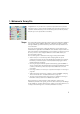
2. Introduction to the Survey Pro User Interface Home Screen and Main Menu On launching Survey Pro, you will first be asked to open a job. When done, the software will open at the Home screen. The home screen shows a selection of the functions you will most frequently use in the field. You can customize the Home screen based on your needs.
Switching Between Home Screen and Main Menu The table below lists the buttons allowing you to navigate between the Home screen and the Main Menu and its submenus. Icon / Check boxes Result Takes you to the Home screen from the Main Menu or any submenu. Takes you back to the Main Menu from the Home screen. Takes you back to the Main Menu from an open submenu. The default Home screen has only one page so there’s only one blue dot (a radio button), and it is necessarily checked.
• Battery Level [3]: The battery icon displays the condition of the data collector’s rechargeable battery. The icon has five variations depending on the level of charge remaining, and a sixth variation to indicate battery charging. Icon Meaning 100% charge remaining 75% charge remaining 50% charge remaining 25% charge remaining Less than 5% charge remaining Battery charging from AC adaptor Tapping the battery icon is a shortcut to the Windows Mobile Power Settings screen.
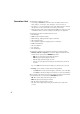
Adding a Function This is a three-step procedure: • Go to the Main Menu, then to the submenu containing the function you would like to add to the Home screen. • Tap and hold the corresponding function item and select Add to Home. Survey Pro then shows the Home screen with all the possible free locations for the new function, all represented as unnamed icons. Note at this point that all the icons are shown with the same background color (see example).
Screen Details The screen example below illustrates the different types of items you will usually encounter on the screen when using the different Survey Pro functions: [1] [4] [3] [5] [6] [2] [7] • Input Field [1]: An area where you can enter a specific value. • Output Field: Only displays a value that cannot be changed. • Simple Button [2]: Typically used to run the function described by its name. Just tap it to run the function.
The following buttons will appear in the area usually occupied by the command bar. Item Function OK button. Accepts the changes made and closes the window. Cancels the changes made in the open window Closes the current window Quick access to the relevant Settings screen Quick access to the Help system Quick access to the Quick Pick list. Map View The map view is a graphical representation of the objects in the current job. It will show basemaps in the background if you are using one (see screen example).
If Optical or GNSS is selected, the main map can also function as an interface to collect measurements. Tap and hold on the main map and choose Survey Mode to enable the Measurement interface (see screen example for GNSS). When in Survey Mode, you can collect data from the main map by tapping on one of the available buttons (see table below). You can also press the Enter key to trigger an observation. By default, the Enter key will trigger a “Topo” observation.
When the survey mode is active: • Tap and select Show Snap To Options from the menu to show both the Zoom toolbar and the Snap-To toolbar. Any of the zoom functions can also be run directly from this menu. • Tap to hide both of them. Zoom toolbar: Button Function Will change the scale of the screen so that all the points in the current job will fit on the screen. Will zoom the current screen in by approximately 25%. Will zoom the current screen out by approximately 25%.
3. Creating a Job Survey Pro cannot start without a job being open. Upon launching Survey Pro, the Welcome to Survey Pro screen will guide you through the process of creating a new job or opening an existing job. NOTE: Upon launching the onboard version of Survey Pro, the initial screen allows you take measurements without having to open a job. Refer to 9. Survey Pro’s On-Board Version on page 82. • Tap the New button.
Job Settings The settings and values entered for a new job become the default values for any subsequent new jobs. A short description of the jobs settings is given below. [1] [2] • Units [1]: When creating a new job, set all the desired units for the job. You can also enable the setting for Earth Curvature and Refraction correction for optical measurements. • Control File [2]: Control points can optionally be imported from another existing job by checking the Use a Control File check box.
• Select Coordinate System [3]: When you are using a control file, you can start the job with the control file’s coordinate system, or you can pick a different coordinate system from the database. If you don’t have a control file, you need to choose the coordinate system for the job.
Importing Data Use the File > Import function to add points to the open job. The points may be imported from different file formats: • Survey Pro native formats (*.Survey, *.JOB, *.JXL, *.CR5). JXL is the extension for files in JobXML format, a Spectra Precision standard format for point, alignment, and measurement data. • LandXML (*.XML), an industry standard format for point, alignment, and measurement data. • Text format (*.TXT, *.CSV).
description. You can also search by point code (FXL auto linework and attribute code). : Will become active only after Survey Pro has found the first point in the list meeting your search criterion. Each new press on this button will view the next point in the list also meeting the search criterion. • • : Allows you to insert a new point to the list. A name will be prompted by default for the new point, based on the name of the currently selected point.
Creating a New Point Select any point in the list and tap to insert a new point: • The General tab allows you to name the new point, add a description if necessary, assign a layer to the point and possibly attach a picture to it (using the built-in camera or by selecting an image file from the disk). • The Location tab allows you to enter coordinates for the point. You can enter Grid, global geodetic (WGS84 LLH) or local geodetic (Local LLH) coordinates.
• Transforming a computed point into a key-in point: Use the Edit Location button on the Location tab to change the two horizontal coordinates or/and the one vertical coordinate. For example, using a total station or GNSS, you observe a point and measure its three coordinates. This point is in addition a benchmark providing an elevation reference. You may want to fix the vertical coordinate to what is written on the benchmark sheet rather than keep the measured elevation.
Generating Survey Reports Survey Pro can generate a report of your survey based on the content of the currently open job and formatted according to the template you chose at the beginning of the process. About 20 templates are available (see list below) and most of them are customizable.
(On the same screen, the View Report button would take you back to the survey report view, and the Another Report button would allow you to ask for a new report, based on the same or a different template.) Sharing Files Over the Internet Survey Pro allows you to share files over the Internet. This requires that you first set up an Internet connection on your data collector using Windows Mobile’s Settings > Connections > Connections function.
4. Choosing a Surveying Mode - Connecting Survey Pro to an Instrument Before you start taking new measurements with Survey Pro, you must configure and activate your instrument. You can activate an optical total station, a GNSS receiver, a digital automatic level, or you can specify to use manual input for three-wire leveling. NOTE: Selecting an instrument only makes sense when Survey Pro is running on a data collector. If it’s running in the instrument you are using (e.g.
NOTE: In surveying, the term "automatic level" refers to a level that can be accurately plumbed without having to be accurately leveled. All levels built in the last 40 years or so have been automatic levels. They are automatic because the prism through which the light rays pass is suspended by a pendulum.
• Tap the Create New Instrument button and define the new instrument: Choose its brand and model, and then name it. Depending on the model you select, additional settings may be required (connection, radio, etc.) and status is also provided (port, connection, level bubble, etc.). An Instrument Settings button is also available giving access to advanced settings (collimation, EDM, lights, etc.). • Tap to create the new instrument and close the Instrument Setup screen.
• Stop button: Stops the current turn or search operation • Turn To button: Opens up the “Turn To” screen where you can select a point or angles to turn the instrument to. The following icons are made available next to the title bar: Item Function Visible laser pointer off. Tapping on this icon will turn the laser pointer on. Note: Standard safety precautions should be taken to ensure that persons do not look directly into the beam. Visible laser pointer on.
GNSS Mode - Introduction to Receiver Profiles Connecting Survey Survey Pro connects to a GNSS receiver through a receiver profile, which is a convenient way of connecting to and configuring a GNSS receiver in one click, Pro to a GNSS using information previously saved as a receiver profile. Receiver Receiver profiles allow you to use GNSS receivers for either RTK data collection, post-processing data collection, or both simultaneously.
Adding Receiver Profiles • Tap the Instrument icon and select Switch to GNSS. • Tap the Instrument icon and select Manage Instruments. This opens the Settings screen listing the currently existing GNSS receiver profiles. • Tap Add Receiver Profile, then use of the two procedures described below. Example of Detected Receivers Example of Selected Standard Receiver Profiles Adding Receiver Profiles Using Spectra Auto-Configure: • Tap on the Start button in the Spectra Auto-Configure pane.
NOTE: The Bluetooth Device field lists the names of the previously detected Bluetooth devices. Use this field when the receiver you want to connect to was detected beforehand, is still running nearby, or you know its Bluetooth name and this name is still listed in the drop-down menu. Only in that case can you directly select the Bluetooth name from that list and quickly establish a connection with the receiver.
• [2]: Survey function icon: This may be one of the four icons below (see also Modifying a Receiver Profile on page 28). Icon Meaning Rover. Base. Network Rover. Network base. • [3]: Connection icon: This may be one of the two icons below. Icon or Function Shown when respectively a Bluetooth or cable connection has been set between Survey Pro and the receiver. If the Bluetooth icon is shown, tapping this icon will provide the receiver brand and model as well as the receiver Bluetooth name.
Example of Receiver Information • [7]: This menu is displayed after you tap and hold a receiver profile in the list. From this menu you can do the following: – Receiver Info: Use this function to view more information on the receiver connected to Survey Pro through this profile (see example). The possible capabilities of a receiver (shown as icons) are identified below. Icon Capability The receiver has rover capability. The receiver has base capability.
– Set to Off mode: Sets the receiver idle, i.e. no more corrections are sent out if the receiver is a base –or network base– or the receiver stops listening for corrections if it’s a rover or network rover. There is an exception with ProMark receivers, which in all cases will keep on operating as rovers. Epoch 50’s Modem tab • The Modem tab allows you to configure the RTK data link. – If Setup Type = Rover or Base, allows you to enter the UHF radio settings (i.e.
Example of Network Profile To add a new network profile: • Tap the Instrument icon and select Switch to GNSS. • Tap the Instrument icon and select Manage Instruments. This opens the Settings screen listing the currently existing GNSS receiver profiles. • Tap on the Networks tab • Tap Add Network. Enter your network parameters (see below), then tap .
Checking the GNSS Status Checking the GNSS status of the connected receiver is recommended before starting a job.This implies that the GNSS receiver is in real conditions of use, preferably in an open sky environment. Use the GNSS Status function on the Survey menu to read this information. The GNSS status is split into six different tabs: • Receiver: Provides additional information describing the position solution computed by the receiver.
Leveling Mode Getting Ready for Leveling Leveling can be performed using one of two techniques: • Automatic leveling: An automatic level is used to take readings on a graduated level rod. This is the traditional leveling technique for surveying. It can be performed by manually reading the rod, or by using a digital automatic level such as the DiNi to electronically read the rod. • Trigonometric leveling: An optical total station is used to measure zenith angle and slope distance to a prism on a pole.
Choosing Leveling Mode 1. If your active instrument is an electronic automatic level, then Survey Pro will automatically use Electronic leveling method. 2. If your active instrument is an optical total station, then Survey Pro will automatically use the Trigonometric leveling method.
5. Optical Surveying What you have done already: • You have set up the optical instrument on a tripod over a point of your choice and measured the instrument height. • You have selected Optical from the instrument icon located on the Home screen or Main Menu. • You have activated the instrument for use with Survey Pro. See Optical Mode - Connecting Survey Pro to an Optical Instrument on page 21. • You have configured the proper settings in the Job > Settings > Surveying tab.
Instrument Setup Station Setup on a Known Point The name and coordinates of the known point where the station is set up can be picked from within the open job. This method offers three different scenarios: • BS Azimuth [1]: Backsight azimuth. The station location will be set from the coordinates of the known point. The circle is set using the value you enter in the Backsight Circle field. The backsight azimuth will be the value you enter.
Start the station setup as follows: • Go to the Main Menu, then tap Survey > Station Setup. • Choose Setup Type= Known Point. • Enter the name of the station setup point in the Occupy Point field. The point name can be entered directly, or, picked from the map or point list using the button. • If you wish to ignore elevations in your job, check the 2D Survey box. You will otherwise enter the HI (height of instrument) field. • Tap Next.
2. If you choose BS Point: • Enter the name of the backsight point. It can also be picked from the map or the list of points. • Specify the type of target used at the backsight point (Fixed Target or Roving Target). A “roving target” is when you measure to the backsight with the same rod and prism you will be using for your subsequent data collection.
you choose New Point: Place a target at the unknown (new) backsight point. Aim the instrument at this point. Enter the known or an assumed value of azimuth along this direction. Enter the desired value of backsight circle for this direction (typically “0” or true azimuth). If the Survey with True Azimuths setting is enabled, then the circle value will automatically be set by Survey Pro. – Tap Set Circle. – Specify the type of target used at the backsight point (Fixed Target or Roving Target). 3.
• Go to the Main Menu, then tap Survey > Station Setup. • Choose Setup Type= Unknown Point/Resection. • Use the Store Pt and Description fields to enter respectively the name and description of the point where the instrument is set up. (This is a new point, with unknown coordinates.) • If you will ignore elevations in your job, check the 2D Survey box. You will otherwise enter the height of instrument in the HI field. • You can take one or more shots of each point.
• At this stage, you can tap Finish to complete the station setup. The instrument circle used for this setup will be the direct circle reading on the first resection point used in the setup, unless you are surveying in true azimuth mode. In true azimuth mode, the instrument circle will be adjusted so that your circle will now read the true azimuth when pointed at the first resection point used in the setup.
Remote Elevation This routine will set the elevation coordinate of the station from a point with known elevation. It is accessible from within the first station setup screen by tapping the Remote Elevation button (provided the 2D Survey box is unchecked). The point with known elevation is either: • A point stored in the job. You will select it from the map or the list of points.
Sideshot • Be sure the instrument is pointed at the target placed over the point. • Tap Sideshot. Survey Pro returns the results of the measurement in the lower portion of the screen ([1]). The point name is automatically incremented for the next measurement. Tapping on the Result tab will provide more information on the measurement made ([2]). [1] [2] Point: Point name N: Point coordinate Y E: Point coordinate X Elev.
Traverse • Be sure the instrument is pointed at the target placed over the point. • Tap Traverse. The screen prompts you to measure a new point, or to pick a point that was previously measured from the current station setup (Survey Pro will display a list of appropriate points), and then move the instrument to that point. If you create a new point to traverse to, you will then be asked to enter the description of the point before measuring it.
Repetition Shots The Repetition shots function allows you to perform sideshots or traverse shots using any number (between 1 and 99) of repeated measurements (“Sets”). • Go to the Survey menu and tap Repetition Shots. • Tap in the command bar to access the job settings relating to repetition shots (equivalent to navigating to the Job > Settings > Repetition tab). • Tap the Repetition tab.
EXAMPLE: If you had three complete sets, then selected to toss the worst HA, you would now have two HA sets, three ZA sets and three SD sets. If you tapped HA, you would collect an additional set of horizontal angles only, and on return to this screen, you would now have three HA, three ZA, and three SD sets. If you hit HA again, on return to this screen you would have four HA, three ZA and three SD sets.
6. GNSS Surveying Starting an RTK Base NOTE: You don’t need to set up a base if you are working in a network. Just make sure your rover is configured to receive network corrections, and actually receives them before you start taking measurements in your job. See Starting an RTK Rover on page 48. What you have done already: • You have set up the base GNSS receiver on a tripod over a point of your choice and measured the antenna height.
2. Mapping Plane: Tap on this button if you now wish to use a coordinate system (i.e. known origin and type of projection + known datum or broadcast RTCM datum) that can either be keyed in or picked from Survey Pro’s coordinate system database. For more information on the projection mode, refer to Introduction to Calibration on page 57.
Starting an RTK Rover This section describes how to configure and start an RTK rover. What you have done already: • You have set up the GNSS receiver on a pole and measured the antenna height. • You have selected GNSS from the instrument icon located on the Home screen or Main Menu. • You have created a receiver profile that matches the use of your receiver as a rover (or network rover) and the receiver has been reported as being “rover” capable.
• While the rover receives data (corrections and position) from the base, enter the rover antenna height you measured previously (Measured field) and how you measured it (To field). You may ask the rover to log raw data (for post-processing) by just specifying a recording interval in the Post Processing Recording Interval field. If you earlier set up a base doing the same, then make sure you are using the same recording interval for both receivers. Select “Off” if data logging is not required. • Tap Next.
If the Next button is displayed instead, this means you are working in Default Ground mode, where a calibration is always required, or you are working in mapping plane mode but you started your base on a new point with a new autonomous position. Tap this button. You will see a new screen asking for occupation of control points (see screen example). For the sake of clarity, calibration is discussed in a separate section (see Solving Calibration on page 57).
Independently for each type, you can set the following criteria: – Solution quality: “Fixed only” or “Code, Float or Fixed” – Max. tolerated HRMS and VRMS values – Max. tolerated PDOP value – Minimum number of satellites required (Min SV). – Minimum position averaging time, in seconds (Average for) – Automatically accept data collection or not when criteria are met. NOTE: The last two criteria make sense when the receiver is set to static to give the best averaged position.
From the Data Collection screen, you can perform several types of point collection: • Point: Tap this button to collect the averaged position of a point after a timed, static occupation on that point. The acceptance criteria defined on the Data tab will apply. (The corresponding markers will be inserted into the GNSS raw data file if raw data logging for post-processing is activated.) • Topo SS: Tap this button to collect the “instant” position solution of a point.
• Automatically accept when criteria is met checked: The use of this parameter makes sense when it is combined with Average for checked. Survey Pro will automatically store the point at the end of the averaging time, unless some other acceptance criteria are not met. In that case, at the end of the count down, the Accept button will be restored on the screen and when you tap on it, you will see screen type [3].
Collecting Features Tap Feature on the Data Collection screen. Features can be collected using one of the methods below. In all methods, each new point name is incremented automatically to the next available name. • Time Interval: After accepting the first point, additional points will automatically be stored after the specified time interval (in seconds) has elapsed.
Collecting Offset Points • Tap Offset on the Data Collection screen. • Enter the offset point name and description. • Tap Azimuth/Bearing to indicate that you will be measuring either the azimuth or bearing angle from the occupy point to the offset point.
Collecting Data Out of a Survey If you tap Data Collection on the Survey menu without having first started a survey, Survey Pro will invite you to choose between two options: • Start the survey first, then collect data (this is the recommended way of using Survey Pro). • Start collecting data right away (and possibly running any stakeout routines) using your receiver in Autonomous Rover mode, that is, with the receiver only capable of delivering autonomous position solutions.
Solving Calibration Introduction to Calibration A GNSS calibration is a 2D similarity transformation. The GNSS LLH coordinates are transformed using a map projection into XY mapping plane coordinates. The XY mapping plane coordinates are then translated, scaled and rotated into your local grid using the calibration. Your choice of projection mode will determine the mapping plane used for this procedure: 1.
Calibration Procedure, Illustrated The calibration procedure can be split into three distinct steps. These are described below as flowcharts: • Step 1: When you start a survey, Survey Pro will report the need for calibration on the Calibration Status page, which will guide you through the process of collecting the minimum amount of control points required for a unique solution of the calibration.
• Step 2: The Calibration check page will guide you through the process of collecting an additional GNSS control point to check the solution, and to provide redundancy for the best fit least squares solution.
• Step 3: The calibration results page will solve the calibration and display the results. From Step 2 Control points are spaced evenly and have good geometry? Yes Blunders Detected Blunder Detection Runs No Yes No No Blunders Detected Tap Finish to accept the solution anyway To Step 2 Tap Add Point to collect more control points, as in Step 2.
After you have solved the calibration as part of the Start Survey wizard, you can use the Survey > Control > Control routine, or the Survey > Projection > Solve Calibration > Add Point routine to add additional GNSS control points, re-solve the calibration, and have all the collected points updated with the latest calculation.
With a known coordinate system used: • If you set up the base on a known point, the selection of a known coordinate system will allow Survey Pro to compute and attach the equivalent geodetic (LLH) coordinates to that point. • If you set up the base on an unknown point: Same as with no coordinate system used. Unexpected Change of Base Typically when working in a VRS network, your rover may detect a change of base location in the corrections it receives. In that case Survey Pro will warn you of that change.
• For a “temporary” reference point ( (survey)), you can use the context menu to save the reference point to the reference station database. Ending a Survey Go to the Home screen and tap End Survey. Confirm the end of survey by tapping End. A survey in progress implies that either a base or a rover or both are running. You will need to end the currently running survey if you wish to reset the base or rover.
7. Leveling Introduction What Leveling Is Leveling is a surveying method that allows the most accurate measurement of vertical distances between points. Using a starting point with know elevation, the leveling survey method allows you to transfer the elevation to new points by measuring vertical distance differences between the know elevation and the position of the level instrument. Leveling data collection is organized into level loops.
• • • • • A level loop can have two states: open or closed. Once a new loop is created, it is automatically opened. It will remain open until you decide to close the loop. A level loop is closed after shots are taken to the closing CBM. Level loops are stored within the current Survey file, which can contain any number of level loops. Any level loop can be selected from the current job as the active loop for data collection. Once a loop is closed, it cannot be re-opened for data collection.
Creating or Selecting a Level Loop • From the main menu, tap Survey > Select/Create Loop. NOTE: Survey Pro will list all the level loops that haven’t been closed yet. You may select one of them and tap Activate Selected Loop to choose to work in this level loop. • To create a new level loop, tap on the New Loop button. This opens the New Level Loop screen. • Enter a name for the new level loop (e.g. MyLoop). • Tap on to define the opening CBM.
Collecting Elevations Description of a Simple Level Loop in an Open Level Loop A simple level loop is illustrated below. BS FS FS TP3 BS TP4 BS BM1 FS FS BS BM2 TP2 BS FS FS BS TP5 TP1 BS FS FS TP6 BS BS FS BM3 FS BS BS FS Opening & closing CBM TP7 Collecting elevations in a simple level loop consists of the following: 1. In every level loop, you will start with a backsight observation to the opening CBM. 2. You will observe some number of turning points next.
1. The instrument is set up somewhere close to the maximum allowable sight distance (typically 30 meters) away from the opening CBM. A backsight observation is taken to the opening CBM. 2. A foresight observation is made to the first turning point. This turning point should be chosen in such a way that the instrument is located midway between the opening CBM and that turning point. Steps 1 and 2 are called the first turn, and are indicated as BS and FS in the above diagram.
Collecting Elevations in a Simple Level Loop After creating/selecting a loop, Survey Pro prompts you to start collecting elevations in the loop. A new screen is displayed providing the list of possible actions. The name of the open level loop is indicated in the upper bar. NOTE: The page 33). button provides access to the level settings (see Level Settings on • • Slope Dist. • Zenith • • Hor. Dist. • Vert. Dist.
6. Move the instrument for the next level turn and then start a new shooting sequence. If the foresight point is a turning point, tap Turn to Turning Point again. If the foresight point is a point of interest (i.e. a benchmark), tap Turn to Benchmark. In both cases, proceed as explained above. Again, Survey Pro will provide results at the end of the second level turn that you will need to accept by tapping Store Observation.
Collecting Elevations for Sideshot and Stakeout Points Sxn Sx1 Sideshot or Stakeout Points Sx1.. Sxn FS BS FS TP3 BS TP4 For some level turn, you have made your backsight measurement to the previous turning point or benchmark. At this stage, the elevation of the instrument is known. Before completing the turn with a foresight measurement to the next benchmark or turning point, you can shoot any number of sideshot or stakeout points.
Adjusting a Closed Loop Adjustment may be used to remove the error computed from any existing closed loop. This is a simple arithmetic adjustment where the computed error can be either distributed equally among each instrument setup in the loop, or a weighted adjustment can be applied where the error is distributed based on the length of the backsight and foresight distance of each turn. 1. From the main menu, tap Survey > Adjustment 2. Choose how you want Survey Pro to distribute errors.
Running the 2 Peg Test The 2 Peg test is used to check the collimation error of an automatic level instrument. This test can be used for electronic automatic levels and manual automatic levels. The test will compute the error, which can then be used to adjust the horizontal cross-hair of the instrument. 1. Position two rods 50 to 90 meters apart (165 to 300 feet). 2. Pace off the distance between the rods and set up the level midway between them.
8. Stakeout Routines This section introduces the basic stakeout routines with optical and GNSS instruments. When you become familiar with these routines, you will be able to extend your knowledge on more specific stakeout routines, such as stake to line, slope staking, etc. What you should have done already: • You should have now completed the station setup with your optical instrument. • You should have now solved the calibration with your GNSS receiver.
The following appears when zeroing the circle: – A new backsight circle value is computed, sent to the instrument and stored in the raw data. – The Angle Right value is changed to zero to reflect the change (see example). The instrument now needs to be turned horizontally to zero to face the design point. – To prevent errors, the backsight setup is invalidated when exiting the Stakeout function.
Staking Points With a Robotic Optical Instrument • Go to the Stakeout menu and tap Stake Points. • Use the Design Point field to enter the name of the first point you want to stake. • Enter an integer in Increment. This will allow Survey Pro to automatically select the next design point to stake once the current one has been staked. e.g. “ST101” first staked and Increment= 2, then next point will be “ST103”.
When you get closer to the design point, the graphic will change to assist you in more precisely locating the design point. The point to stake becomes the fixed center of the display and the rod becomes the object that is moving. This aids in precisely positioning the rod over the point. A red arrow indicates the direction in which to go. 1. Distance to go is between 3.0 and 0.3 m (10 and 1 ft): Four dark-green spots appear around the graphic. 2. Distance to go is less than 0.
Staking Points With GNSS • Go to the Stakeout menu and tap Stake Points • Use the Design Point field to enter the name of the first point you want to stake. • Enter an integer in Increment. This will allow Survey Pro to automatically select the next design point to stake once the current one has been staked. e.g. “ST101” first staked and Increment= 2, then next point will be “ST103”. (Tapping the Next Point button will instantly select the next point from the list, based on the Increment value.
Remember the rover receiver is always in dynamic mode (>ROVING button displayed) as you navigate to the design point: Symbol Meaning Design point location. Your current location. Reference point or azimuth. Scale used on the graphic. Represents the circle radius. Go N/S: xxx Go E/W: xxx Horizontal and vertical components of the distance still to go. FILL/CUT: xxx NOTE: You can use the Topo SS button any time along the way to store any point of interest.
• When you have located the design point and you wish to collect a static RTK occupation at this point in order to get a more precise position averaged from multiple epochs, you should toggle to occupying mode by tapping the >ROVING button (which is then changed into an >OCCUPYING button). This will turn the receiver into static mode for the occupation. • When you are satisfied with the occupation results, you can tap Accept to finish the stakeout measurement.
• Stake to Line: Allows you to locate any position in relation to a predefined line. The line can be defined by two points, a point and direction, a polyline or the centerline of an alignment. Distance, direction and cut/fill information is provided so the rod/the rover can locate the line by traveling the shortest possible distance (a perpendicular offset to the line).
9. Survey Pro’s On-Board Version Survey Pro is used on board a Nikon Nivo or Spectra Precision FOCUS total station. After you have powered on the instrument, wait until the screen displays the desktop. Then do the following: • Double-tap the Survey Pro icon: . Survey Pro starts initializing the instrument. The Level Bubble screen is then shown (see screen example). • Level the instrument and enable or disable the compensator, as required. • Tap when done. This opens the Quick Shot screen.
Mechanical Instrument: [1] [3] [4] [5] [6] [7] [8] [9] [10] [13] [14] [15] [16] [17] Command bar: • [1]: Provides access to on-board help. • [2]: (Robotic instrument only) Denotes keyboard used in numeric mode. • [3]: Provides status of visible laser pointer: – : Off. Tapping this icon will toggle it On. NOTE: Standard safety precautions should be taken to ensure that persons do not look directly into the beam. – • • • • : On. Tapping this icon will toggle it Off.
• [8]: Provides access to Survey Pro settings: – Units tab: Used to set distance and angle units, directions, azimuth type and the order in which to display/deliver coordinates. – Format tab: Used to set the number of decimal places displayed by the instrument for each type of measurement. – Quick Shot tab: Used to choose which results to display (HA, ZA, SD or HA, HD, VD) and which function to assign to the Measurement key (Measure Only or Measure and Store). Measure and Store requires an open job.
Target management: (Item [15]) on the screen example.) • HR field: Enter the height of rod for the selected target • / button: Specify the type of target used. Also provides access to the management of smart targets. • Choose the EDM measurement mode.
Working With a Job Open If you open or create a job using button [13], the Quick Shot screen will then show different options. Robotic Instrument: [10] [11] [19] [12] [13] [20] Mechanical Instrument: [10] [13] [19] [20] The differences are listed below: • [10]: With a job open, the Quick Stake screen can be accessed through this button. The Stakeout, Station Setup and Check Setup functions can be accessed by clicking on the arrow to the left of this button. • [11] and [12]: Same as with no job open.
Shot tab if you plan to store measurement data (see [8] described earlier in this section). With a job open, you can perform a lot of the most commonly used functions from the Quick Shot screen. To access the full set of Survey Pro functions, you can close the Quick Shot screen and access the Survey Pro main menu. Survey Pro can be used either in optical or leveling mode. NOTE: To access the Quick Shot screen at any time, simply press the “star”/F1 hard key on the instrument.
Appendix Advanced Information Descriptions on Point Properties A description may be defined for each point you store in a job (e.g. tree, [1] [2] pavement). You can create a description list to automate the task of entering descriptions for points when they are stored. This is particularly useful when the same description is used frequently. A description list is stored in Survey Pro as a description file (a TXT file you store in /Survey Pro Jobs/ for example), which may be in two different formats.
Features & Attributes Features can be used to quickly describe objects (points, lines), and in more detail than a standard text description, particularly when data is collected for several points that fit into the same object (e.g. a line). A feature describes what an object is while attributes describe the details of that object. Features and attributes can be entered as you collect data, or later by editing the points in your job.
Adding/Modifying Features By Editing Points: • Go to Job > Points. • Select the point for which extra features are required, or attributes need to be corrected. • Tap then open the Feature tab. • Tap to add a new feature (and define its attributes), or directly edit the attributes of the existing features if necessary.
Survey Pro allows you to customize the note editor so you can enter your notes more quickly. Up to16 buttons are made available for this purpose. Through each of them, you can preset up to 127 characters of text and/or numerals, The label of each button (5 characters max., also editable). should reflect the character string held by the button. While creating or modifying a point, do the following to customize a button: • Tap on the Notes tab. • Tap on the Add Note button. • Tap Customize.
The Raw Data Viewer is fitted with a toolbox that you can use as explained below. Icon Function Takes you to the first action logged in the job. Takes you to the last action logged in the job. Takes you back to the previous action you highlighted in the list of actions. Valid only after you have used the left-arrow button just above. Allows you to scroll back through the different actions you went through previously with the left-arrow button.
Memo for GNSS Users Assuming the following: • A receiver profile has been created previously so you can use your RTK rover in a network. • If you are using a “network rover”, a network has also been defined previously for the purpose of receiving corrections from an IP server. (No network profile needs to be created if you are using a “rover” receiving corrections from a base via radio.) • A new job file needs to be created in which a known coordinate system and a geoid are used.
Managing Smart Targets 94 In earlier versions of Survey Pro, there was a separate list for backsight and foresight targets. With Survey Pro 5.2 and 5.3, there is now a single list of optical targets, so you can choose to take an observation to any target from any measurement routine. This enhancement makes certain routines, such as repetition, multiple sideshots and shoot from two ends, much easier to use.
Index Numerics 2D Survey 36, 39, 41 3D position solution 31 A Accept Anyway 53 Acceptance criteria (GNSS) 50 Activate 22 Active map 8 Add Receiver 25 Add to Home 6 Adjusting a close level loop 72 Alignments 17 All 44 Allow in PPK Survey 51 Angle only 39 Angle Right 42 Angle right 75 Antenna type 49 Attributes 89 Automatically accept when criteria is met 53 Autonomous rover mode 56 Average for 51, 52 Average of 44 Azimuth 55 Azimuth (entering) 2 Azimuth/Distance 78 B Backsight 40, 41 Base (change) 62 Bas
KOF format 18 L LandXML 14 Layer 14 Layers 16, 88 Level bubble 22, 82 Level loop 1, 64, 67 Level loop report 18 Level settings 33 Level turn 65 Leveling 1, 20, 32, 64 Leveling mode (choice of) 33 Lights 22, 83 Line and Offset 81 LisCAD 18 LLH 2 Local geodetic 16 LockNGo 84, 85 LockNgo 22 M Main menu 3 Manage Instruments 20, 25, 26, 27, 28, 30 Manual Prompt Every Point 54 Manual Configuration 24 Manual mode 21 Manual Prompt Once 54 Map projection 13 Map view 4, 8 Mapping plane 47, 48 Meas.
Start Manual Setup 25 Start Now 50 Start Survey Prompt Projection 48 Station Setup 36, 39, 86 Stop 23 Store Offset Points 81 Store Pt 39 Submenus 3 Survey (file format) 14, 17 Survey Mode 51 Survey reports (generate) 18 T Tab 7 Take Shot 39 Tap and hold on menu items to manage the Home screen 5 Three-wire leveling 20, 32 TIFF 8 Time Interval 54 Topo SS (acceptance criteria) 50 Topo SS (data collection) 52 Toss 44 Track light 85 Tracking 85 Transform computed point to key-in point 17 Traverse 41, 43, 45, 86
Survey Pro User Guide SPECTRA PRECISION Survey Support: Email: support@spectraprecision.com technical@ashtech.com US & Canada: +1 888 477 7516 Latin America: +1 720 587 4700 Europe, Middle East and Africa: +49 7112 2954 463 Australia: +61 7 3188 6001 New Zealand: +64 4 831 9410 Singapore: +65 3158 1421 China: 10 800 130 1559 Contact Information: SPECTRA PRECISION DIVISION 10355 Westmoor Drive, Suite #100 Westminster, CO 80021, USA www.spectraprecision.