VENTURA 150 MPC-5000 OWNER’S MANUAL Section 1…………..Installation, Operation, Maintenance Section 2………………….……...Controls & Programming Spectra Watermakers, Inc. 20 Mariposa Road, San Rafael, CA 94901 Phone 415-526-2780 Fax 415-526-2787 E-mail: spectra@spectrawatermakers.com www.spectrawatermakers.com Rev.
Table of Contents Section 1 Installation Page Number Introduction ......................................................................................................................... 5 Getting Started..................................................................................................................... 6 Installation Basics ............................................................................................................... 7 Ventura Plumbing Schematic.........................
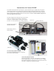
Introduction to the Ventura 150 MPC The Ventura represents the finest watermaker for small and midsized yachts available today. The Spectra Clark Pump is matched to a 21” high rejection membrane. Properly installed and maintained it will supply years of reliable service. The MPC-5000 control provides the ultimate in operational convenience and reliability. Note that prudent operation is required with any marine equipment. Always maintain enough reserve water to get safely into your next port.
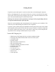
Getting Started Unpack the system and inspect it to make sure that it has not been damaged in shipment. Refer to the shipping list for your system to make sure you have received all of the components listed. Do not discard any packaging until you have found and identified all of the parts. The small installation parts are listed on the kit list. Warning! We will not be held responsible for shortages and/or freight damage that are not reported within thirty days of the ship date.
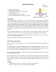
Installation Basics • • • • • Thruhull Not Supplied. Read the directions! Avoid tight hose bends and excessive runs Use heavy gauge wire Install feed pump as low as possible Use a dedicated thruhull with scoop type strainer Flow Thru-hulls It is mandatory that a dedicated 1/2” to 3/4” forward facing scoop type intake thru-hull and seacock be installed. Install the intake for the system close to the middle and as far below the water line as possible.
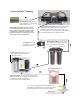
Ventura 150 MPC Plumbing Brine Discharge thru hull place above waterline or tee brine into another visible drain. Plastic fittings should have 3-4 wraps of Teflon tape and will thread almost all the way in. Leave the first pipe thread uncoated. Avoid getting dirt or debris in the system during assembly. Avoid tight bends and elbows. Secure piping away from moving objects and protect from chafe. Accumulator, Factory pre-charged. Install so that gauge is visible. Spectra Clark Pump.
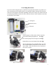
Feed Pump Relocation If you do not have adequate space to install the feed pump inlet module it is possible to remove and relocate the feed pump. Before you install the module, disconnect the hose that connects the feed pump to the module plumbing. Remove the cooling fan and the heat sink from the pump. Both are friction fits with no fasteners. Remove the 4 machine screws holding the pump to the module. Cooling fan Machine Screws Heat sink With the pump on a flat surface.
Product Water Plumbing Product water tubing is 1/4”(6mm) on the Ventura 150 models. See the Parker tube fitting assembly diagram next page. Product water is pre-plumbed from the membrane into the electric diversion valve. The diversion valve will reject product water into the overboard brine stream until good quality is measured by the MPC-5000 control. Product water is then diverted into the fresh water tank. Product to tank.
Product Tube Fitting Assembly Body Step 1: O-ring Spacer Grab Ring Nut Tubing Dissemble fitting components 1/2" max Step 2: Install the Nut first then use the bevelled side of the Spacer to push the Grab Ring onto the tube no more than 1/2". Slip the O-ring over the tube to hold the Spacer in place. If the Grab Ring is pushed too far, trim back the tube so about 1/4" of tube extends past the O-ring. Step 3: Gently fit the tube into the body and loosely thread on the nut.
Membrane Pressure Vessel Relocation Use ONLY Dayco Imperial Nylo-Seal 88-NSR-1/2 tubing for high pressure connections. Pay attention to the direction and flow path of the tubing before disassembly. Make sure that you reinstall the tubing in the same manner. Rotate the 90 degree high pressure tube fittings on the Clark Pump for ideal tube runs. The high pressure fittings are typically preinstalled at the factory. These fittings seal with an O-ring and require no Teflon tape or pipe dope.
Spectra High Pressure Tube Fitting Assembly Use ONLY Dayco Imperial Nylo-Seal 88-NSR-1/2 tubing for high pressure connections. Carefully fit and measure the tubing before cutting with a sharp razor knife or hose cutter and remove any burrs. Minimum tubing bend radius is 6”. Route tubing away from excessive heat sources and secure from vibration and chafe. Have at least one shallow bend in the tube assembly after it is installed. Refer to figure 1. If a fitting has been dissembled, reassemble as illustrated.
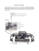
MPC-5000 Wiring Mount the control box on a vertical surface with the wire grommets down, central to the other system components. Make sure the cables will reach all of the modules to avoid splices. Filter Sensor harness 6’ (2M) Control cable 50’ (15.2M) Protect connector while routing through the vessel. Control Box MPC-5000 display. Mount in dry central location. Only connect the MPC “plug in” cable. Fresh water flush feed 15’ (4.5M) Splice to flush valve. Heat connectors to shrink. Pump feed 4’(1.
Clark Pump Harness Salinity Probe Roto Flow meter. Diversion Valve. To Roto Flow Meter To Diversion Valve To Salinity Probe The RotoFlow meter measures product flow. It is supplied with a three pin plug-in connector. Plug it in to the RotoFlow cable and seal the connection with the supplied heat shrink tubing. The salinity probe uses a telephone style jack and plug. Plug it in and slide the black plastic boot over the sensor to waterproof the connection. The diversion valve cable has two conductors.
Tank Switch Installation and Operation: There are two sets of terminals on the MPC-5000 PCB that can be used in four different configurations to automatically start and stop the watermaker, or to automatically stop the watermaker when the tank(s) are full without the auto start feature. These terminals are on the green ten pin connector and are labeled “Float Switch 1” and “Float Switch 2.” Float Switch 1 is the tank full switch and Float Switch 2 is the tank empty switch.
Ventura MPC New System Start-Up and Testing Avoid running the Ventura system if the vessel is in contaminated water, such as in a harbor or canal. The system should be fully tested before leaving port. If the location or weather prevents proper testing refer to the section “Dry Testing.” Warning! Damage may occur if the purge sequence is bypassed and the membrane is pressurized with storage chemical in it. First check that: • • • • • Thru-hull inlet valve is open and the brine discharge valve is open.
The system will go into a start mode and the feed pump will start shortly after. The system should prime within 60-90 seconds. Check the strainer and the brine discharge for water flow. There should be few bubbles anywhere in the intake hoses and the feed pump should sound smooth after priming. After confirming that the system is primed, inspect for leaks. Note: The reject light will be on whenever the product water is being rejected or not being made.
MPC Display Modes Scroll through the modes with the alarm display key. Product The Ventura will produce 6- 6.5 GPH (26-27 LPH) Salinity This may not show any lit bars on a new system. Each square represents 100 ppm. System rejects water higher than 750 PPM. LED lights (Reject, Good) indicate product mode. Feed Water Pressure range 60-70 PSI (4.2-5 BAR) Filter Condition When filters become partially clogged the MPC-5000 will alarm “Service Prefilters”.
Ventura MPC Dry Testing With Artificial Ocean If it is not possible to test run the system with the boat in the water, testing may be accomplished with an artificial ocean. Purchase enough aquarium salt to make 5 gallons (20 liters) of salt water. Make sure that the domestic water system is powered up and that there is water in the tank. Confirm that the charcoal filter is installed in the fresh water flush module and that the domestic water line had been installed and all valves are open. 1.
Ventura MPC Operation Normal operation If the system has been pickled or stored, use the “New System Startup” procedure. 1. Check to see that the inlet seacock is open. 2. Push the “Auto Run” one or more times. The machine will run for one hour for each time the button is pushed, then shut off and automatically do a fresh water flush. If you receive a “System Stalled” error code, there is no flow in the system. Open the pressure relief valve on the Clark Pump and bleed the air out of the feed pump. 3.
Flush Cycle Adjustment Before shipping from the factory the Ventura watermaker flush cycle is set to factory default settings. After initial start up, and annually thereafter, the flush cycle parameters must be adjusted to ensure that the salt water is thoroughly flushed out of the machine while at the same time using the least amount of fresh water possible. Check the flush by closing the sea cock.
Manual Operation In the event of a component failure resulting in a shut down due to a false alarm, the failed component can be overridden using the Programming Function on the display. High Pressure, Service Prefilter, System Stalled (airlock), and Salinity Probe Failed can be defeated. The other safety shutdown will still be activated. The pressure sensors and salinity probe can also be calibrated from the display.
Long Term Storage Procedures Watermakers are best run continuously. When not in use, biological growth in the membrane is the leading cause of membrane fouling. A warm environment will cause more growth than a cold environment. The fresh water flush system will greatly reduce biological growth but may not stop it completely in certain conditions.
Ventura MPC Storage Procedure 1. Shut the service valve by moving it to the middle position. 2. Perform two fresh water flushes by pushing the “Auto Store” button . 3. Remove the cap on the service port on the feed pump module and install the service hose from your kit. Remove the quick disconnect fitting from the brine discharge outlet of the Clark Pump, and replace with a quick disconnect service hose from your service kit. Lead the hoses to a 5 gallon bucket or container. 4.
Winterizing 1. Close yellow service valve, push “Auto Store” to flush the system. 2. Connect the inlet service hose and the brine discharge service hose. Place them in the service container or bucket. 3. Push “Auto Store” and run until there is 1 gallon (4L) of fresh water in the bucket, then stop the system. 4. Reconnect the brine overboard hose to the Clark Pump 5. Turn the service valve to the “Service” position. 6. Pour 2 gallons (8L) of Propylene Glycol in the bucket. 7.
Maintenance General Periodically inspect the entire system for leakage and chafe on the tubing and hoses. Repair any leaks you find as soon as practical. Some crystal formation around the Clark Pump blocks is normal. Wipe down any salt encrusted areas with a damp cloth. The Seawater Strainer The sea water strainer’s stainless steel element should be inspected, removed, and cleaned as needed. Be careful to ensure that the thru-hull is closed before disassembly and the gasket is in place before reassembly.
The Membranes The membranes need to be cleaned only when operating pressures have risen 10% due to fouling, or when the product quality degrades. The leading cause of fouling is from biological growth that occurs when the system is left unused without flushing or pickling. Fouling from mineral scaling can happen during operation under certain sea water conditions, and from rust. Monitor the product salinity and feed pressure for higher than normal readings for the existing conditions.
Spectra cleaning compound (SC-2 or SC-3) must be mixed with fresh water at a ratio of 1 container of compound to 3 gallons (12L) of unchlorinated water to have the proper solution. An average of two gallons (8L) of water is already present inside a Ventura 150 system . This water has to be figured into the mixture. A Ventura 150 system will use one container of compound. Cleaning Procedure: 1. Close the service valve and push “Auto Store” to effect a fresh water flush. 2.
Suggested Spares Ventura MPC Short term cruising, weekends etc. A basic cruise kit B. This kit consists of three 5 micron filters, three 20 micron filters, and SC-1 storage chemicals. Cruising 2 to 6 months at a time. Two basic cruise kits, one replacement charcoal filter, and one replacement feed pump head. Longer than 6 months Additional filters, offshore cruising kit consisting of Clark Pump seals, O-rings, tools and membrane cleaning chemicals.
Ventura MPC Troubleshooting Procedures SYMPTOMS PROBABLE CAUSE REMEDY Feed pump runs constantly, will not turn off Manual override switch in “on” position Turn off manual switch on control box Feed pump runs with loud noise - Intake blocked - Air in system - Check thru-hull valve - Check sea strainer for leaks - Check FWF module for leaks - Re-prime system (restart) No lights or display, system does not operate - Remote display not connected - No power to control box Pumps run intermittently, cyc
Ventura MPC Troubleshooting Procedures Error Messages SYMPTOMS “System stalled” (“system stalled” may alarm when using the control panel to run system for servicing with the pressure relief valve open– use manual override switch instead) PROBABLE CAUSE - pressure relief valve open intake thru-hull closed airlocked system no signal from RotoFlow meter REMEDY - Close pressure relief valve - Check thru-hull - Verify stroke sensor fully inserted in pump - Check stroke sensor wiring at control box - Replace f
ACCUMULATOR PRESSURE All Spectra Watermakers, except the Newport 700 and 1000 series, are supplied with a pressure accumulator tank (part no. PL-ACC-TK) to be installed in the feed water line between the prefilters and the Clark Pump. In addition, the Catalina 300 and Newport 400 series also have an accumulator mounted inside the fresh water flush module. The purpose of the feed line accumulator is to reduce the spikes in the feed pressure caused by the cycling of the Clark pump.
OP-2 BAD SMELLING PRODUCT WATER The reverse osmosis membrane is permeable by many gases including hydrogen sulfide, the gas that causes rotten eggs to smell the way they do. If there are bad odors in the feed water they will go through the membrane and the product water will be affected. Usually the source of the odor is from the decay of planktonic creatures trapped in the sea strainer and prefilters.
OP-3 CHEMICALS 101 Spectra systems use four types of chemicals: SC-1, SC-2, SC-3, and propylene glycol antifreeze. NOTE: Never use any chemicals with the system pressurized! Always open the pressure relief valve 1/2 turn. Always purge a system containing chemicals for at least 20 minutes unpressurized before pressurizing and making water. The SC-1 is for storage only. It is no longer used as a cleaning chemical.
OP-4 FRESH WATER FLUSH The purpose of the fresh water flush is to replace the sea water in the watermaker with fresh water whenever the system is not operating. The “Auto Flush Mode” on the MPC 3000 changes the fresh water every five days if the system has been idle that long. The watermaker will last longer and operate better if it is always kept filled with fresh water between uses. Most spectra watermakers are equipped with a fresh water flush module.
PF-3 PREFILTERS– ShurFlo Up to four different filters are used on all Spectra Systems using ShurFlo feed pumps to ensure that no damaging foreign materials enter the system. There are 2 or 3 filters in the system to clean the feed water of abrasive materials while the system is in operation, and an additional filter to prevent the entrance of chlorine during fresh water flushing. During normal operation, the feed water is filtered in two stages. First it enters a fine mesh metal sea strainer.
SF-1 SHURFLO PUMP WON’T RUN If the pump has power to it (the fan runs), but the pump won’t run, the first thing to check is the pressure switch. The pressure switch, p/n EL-FP-PS, is located on the wet end of the pump and has two red wires plugged into it. Jump the two red wires together and see if the pump runs. You can safely run the system with the pressure switch jumped, just keep an eye on the pressure gauge and don’t let system pressure exceed 110 psi. Replace the switch when a spare is available.
SF-2 ADJUST SHURFLO PRESSURE SWITCH The ShurFlo feed pumps are equipped with a high pressure cut out switch (part no. EL-FPPS). This is the small black unit on the end of the wetted end of the pump head (part no. PLPMP-SFPH) where the two red wires connect. If the pressure switch is not properly adjusted the pump may cut out each time the Clark Pump cycles and the feed pressure spikes.
HS LF-1 POOR PRODUCT QUALITY With any product water quality issue, you need to check the calibration of the salinity tester that you are using before proceeding. Membranes are not an exact science and two identical systems can have a different product quality result. World health standards deem water of up to 1000 PPM of total dissolved solids acceptable for drinking consumption. We consider any thing below 700 PPM acceptable but not ideal, and anything below 500 PPM excellent.
HS LF-2 FLOW TEST/ SHURFLO Before the test, change all filters and clean the strainer. Make sure that there are no leaks. Check for air leaks, as air in the system will cause low production and erratic salinity. Look for air bubbles in the product flow meter, feed pump discharge hose, and brine overboard hose. Run the system and watch the pressures very closely. Make sure that on each shift everything is even from side to side.
Z-BRANE OPERATION MANUAL Spectra Watermakers Inc. 20 Mariposa Rd., San Rafael, CA 94901 Phone 415-526-2780 Fax 415-526-2787 Email: spectra@spectrawatermakers.com Http://www.spectrawatermakers.
The Z-brane is a revolutionary product which incorporates the Z-Guard High Voltage Capacitive technology into the membrane pressure vessel. Always active, the Z-Brane creates an environment that is unfriendly to bio-film and bacteria. The Z technoalgy also assits in the prevention of scale formation on the membrane surfaces. The Z-Brane allows the system to be shut down or decommissioned for extended periods of time without chemicals or preservatives.
Operation During normal operation the Red LED should be on . Power needs to be supplied to the ZBrane unit at all times that you wish to have the biofouling and scale protection. We recommend that your watermaker be flushed after each use not only to protect the membrane but to prevent corrosion in the feed water system. To achieve full effectiveness thoroughly fresh water flush the watermaker several times before leaving the vessel.
Part Numbers 3/8 NPT Quick Disc. Body PL-QDC-BD3/8 Front View 5/8 Quick Disc.
Part Numbers 1/2” Female Tee PL-TEE-1/2FN 1/2”NPT X 5/8 Hose Barb PL-HBS-1/2X5/8 1/2” Nipple PL-NP-1/2N 3/8”NPT X 5/8” Hose Barb El. Pressure Sensor EL-SSR-150 PL-HBE-3/8X5/8 Filter Housing 3/4”NPT X 5/8 Hose Barb El. Bracket Duplex PL-HBE-3/4X5/8 FT-FHB-10HD 1/4” Street El. PL-MFF-1/4X1/4 1/2” X 1/8” Bushing Reducer PL-BSH-1/2X1/8N Pressure Guage PL-PSG-LP1.5 Accumulator Tank PL-ACC-TK 1-Way Solenoid Valve 12V, PL-SLN-1/4O12, 3/4” Nipple PL-NP-3/4N 1/4”NPT X 5/8” Hose Barb El.
Part Numbers PL-SLN-1/4D12VB 1/4" DIVERSION VALVE 12V W/O VB PL-CKV-1/4M-F 1/4" PLASTIC CK VALVE (M-F) SUB-NP-DVM DIVERSION VALVE MANIFOLD EL-MPC-SP SALINITY PROBE EL-SSR-IFM INLINE FLOW METER SENSOR PL-MTS-1/4X3/8P 1/4"MPT X 3/8" TUBE FITT. ST. PL-FTS-3/8X1/4P 3/8"FPT X 1/4"TUBE FITT ST. REDUCING COUPLING PL-UNN-3/8X1/4N MPC CONTROL PANEL (VFD) EL-MPC-RMCDFD 3/4”-16 ST X 1/2” Tube Fitting El. PL-MTE-3/4SX1/2 3/8”NPTX3/8”Tube Fitting PL-MTS-3/8X3/8P 1/8”FPT X 1/2” Tube Fitting El.
Part Numbers Valve End Block B HP-TB-VEB-B 3/8”NPT Quick Disc. Coupling Body PL-QDC-BD3/8 5/8” Quick Disc.
Part Numbers 3/4” 3-Way Valve PL-VLV-3W3/4 Cooling Fan 12V, 24V KIT-FK-12,24 Feed Pump Heat Sink EL-FP-FPHS Ventura Feed Pump Bracket FM-VT-ITM Feed Pump 12V, 24V EL-FP-12V, 24V 3/8”NPT X 5/8” Hose Barb El. PL-HBE-3/8X5/8 Feed Pump Pressure Switch EL-FP-PS Fig 1 Fig 2 Pump Head Assembly W/Press.
Parts End block B HP-TB-VEB-B Valve block HP-TB-VB End block A Composite cylinder and base HP-TB-VEB-A Brine out HP-CYL-CCA Pressure relief valve HP-TB-BV Center block HP-CB-CB7, Feed in Stainless steel tube HP-CYL-SST Cylinder ring End Cap HP-CYL-R HP-CYL-EC Clark Pump Front View End block A Valve block End block B Reset button Not used Composite cylinder and base Not on all units Alternate brine out High pressure in Test port Center block High pressure out Stainless steel tube Cylinder
HD-CPS-5/16X3 5/16"-3 1/4" SS AH Bolts Spool Assembly Exploded View Spool End Spool Seal Quad Ring Seal Spool Center Quad Ring Seal Spool Seal Relief Valve O-Ring Spool End SO-HPP-RV Annular Rings HP-TB-AR Spool Assembly KIT-HP-10VSA Relief Valve HP-TB-BV Annular Ring O-Rings Mount inside Valve Block SO-HPP-AR Valve Block 5/16"- 2 3/4" SS A.H. bolts Reset button and O-ring End block B Piston O-ring SO-HPP-SP, PS20 HD-CPS-5/162.
Parts Valve port seals SO-HPP-VP Pilot valve port seals SO-HPP-PLP Piston rod HP-CYL-3/4R, Center block cylinder O-rings SO-HPP-ECCB Pilot spool O-rings (4) Mount inside block SO-HPP-PV HP-CB-PVS Pilot spool HP-CB-PPS Pilot valve pin SO-HPP-PS Pin seal O-rings Pilot orifice HP-CB-PO HP-CB-PVPS Pin seals HP-CB-PVCR Clip rings Center block Rod lip seals Mount inside block SO-HPP-PR7, PR10,PR15 Feed in Check valve port O-rings SO-HPP-CVP Check valve assembly Piston to rod O-rings (2) Inside
Parts S.