Spectra Stack Shipping Bracket Installation and Removal Guide SpectraLogic.
Copyright Copyright © 2022 Spectra Logic Corporation. All rights reserved. This item and the information contained herein are the property of Spectra Logic Corporation.
Contacting Spectra Logic To Obtain General Information Spectra Logic Website: www.spectralogic.com United States Headquarters European Office Spectra Logic Corporation 6285 Lookout Road Boulder, CO 80301 USA Phone: 1.800.833.1132 or 1.303.449.6400 International: 1.303.449.6400 Fax: 1.303.939.8844 Spectra Logic Europe Ltd. 329 Doncastle Road Bracknell Berks, RG12 8PE United Kingdom Phone: 44 (0) 870.112.2150 Fax: 44 (0) 870.112.
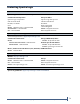
ROBOTICS SHIPPING BRACKET INSTALLATION & REMOVAL This document describes installing and removing the robotics shipping bracket in a Spectra Stack library. The bracket is only required when a Stack library is installed in a data center rack prior to shipping. Estimated Time = 5 - 10 minutes BEFORE YOU BEGIN Before installing or removing the shipping bracket, make sure that you have addressed the following requirements.
Install the Shipping Bracket Ensure ESD Protection Wear a static protection wristband or grounding footstrap whenever you handle components that have been removed from their anti‐static bags. Connect the wristband to the static protection mat or to other suitable ESD grounding. Note: Keep all electronic components in anti‐static bags when not in use.
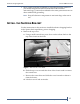
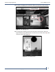
Install the Shipping Bracket Ensure ESD Protection 2. Using a #1 Phillips screwdriver, remove the two screws that secure the slot 5 drive bay cover. Figure 2 The rear of the Spectra Stack chassis. 3. Move the drive bay cover to the slot 1 position at the bottom of the library. 4. Using a #1 Phillips screwdriver, install the two screws you removed in Step 2 to secure the cover to the chassis. 5. Locate the shipping lock inside the library at the front of the chassis. Figure 3 The shipping lock.
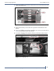
Install the Shipping Bracket Ensure ESD Protection 6. To unlock the shipping lock, from the front of the chassis, slide the latch to the left (1), pull the latch toward the front of the chassis (2), then slide the latch to the right (3). Figure 4 The shipping lock. 7. Grasp the robotic module gently by the sides and pull up to raise the robotic elevator approximately one inch. Figure 5 Grasp the robot as shown.
Install the Shipping Bracket Ensure ESD Protection 8. Using your fingers, raise the robotic elevator using the two cutout holes on both sides of the robot until it is level with the top of the library chassis. It takes approximately ten to 15 seconds to raise the robotic elevator fully. Important Do not raise the robotic elevator higher than the top of the chassis to avoid disengaging the elevator from the track. Figure 6 Use the cutout holes to raise the robotic elevator. 9.
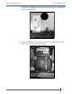
Install the Shipping Bracket Ensure ESD Protection 12. Locate the shipping lock inside the library at the front of the chassis. Figure 8 The shipping lock. 13. To engage the shipping lock, from the front of the chassis, slide the latch to the left (1), pull the latch toward the rear of the chassis (2), then slide the latch to the right (3). Figure 9 The shipping lock.
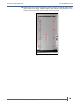
Install the Shipping Bracket Ensure ESD Protection 14. Position the cover over the opening in the chassis so that the tabs on the sides of the cover align with the slots in the chassis, and slide the cover towards the rear of the chassis until it locks in place. Figure 10 The top cover.
Remove the Shipping Bracket Ensure ESD Protection REMOVE THE SHIPPING BRACKET Use the instructions below to remove the shipping bracket after the library is installed in the data center. Important You must remove the bracket prior to powering on the library to avoid an initialization failure. 1. Remove the top cover. a. Using a small screwdriver, press down on the release latch on the top of the chassis at the front. Figure 11 Release the cover latch. b.
Remove the Shipping Bracket Ensure ESD Protection 2. Locate the shipping lock inside the library at the front of the chassis. Figure 12 The shipping lock. 3. To unlock the shipping lock, from the front of the chassis, slide the latch to the left (1), pull the latch toward the front of the chassis (2), then slide the latch to the right (3). Figure 13 The shipping lock.
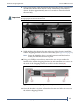
Remove the Shipping Bracket Ensure ESD Protection 4. Using a #1 Phillips screwdriver, remove the two screws that secure the shipping bracket to the chassis (2) and install the screws under the handle of the robotic shipping bracket (1). Figure 14 The robotics shipping bracket rear panel. 5. Using your finger, hold the robotic elevator in place (see Figure 6 on page 8) while you pull the shipping bracket out of the chassis. 6.
Remove the Shipping Bracket Ensure ESD Protection 11. Replace the top cover. Note: Replacing the top cover is only necessary if the Stack base module is the top‐most chassis in the rack. a. Position the cover over the opening in the chassis so that the tabs on the sides of the cover align with the slots in the chassis. Figure 16 The top cover. b. Slide the cover towards the rear of the chassis until it locks in place.