REFERENCE & INSTALLATION MANUAL SPECTRA CONTROL PANELS V2.
TABLE OF CONTENTS Introduction .......................................................................................................................................... 4 Features............................................................................................................................................................................................... 4 Specifications............................................................................................................................
No Exit Delay Beeps and No Bell Squawk When Stay Arming.......................................................................................................... 29 Alarm Options .................................................................................................................................... 30 Bell Cut-Off Timer ..............................................................................................................................................................................
Call WinLoad Software ...................................................................................................................................................................... Answer WinLoad Software................................................................................................................................................................. Auto Event Buffer Transmission ...........................................................................................................
PART 1: INTRODUCTION 1.1 1.2 FEATURES • Up to 16 fully programmable zones • Two completely independent partitions. Many of the features and options in the Spectra System can be independently set for each partition such as event reporting, entry/exit delay, auto-arming and many more. All zones, the keyswitches and all user codes are assigned to specific partitions, which makes this a true partitioned system. • Communication bus facilitates the adding, programming and monitoring of all expansion modules.
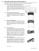
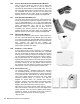
1.3 DETECTORS, KEYPADS AND EXPANSION MODULES If you would like to obtain more information on our line of keypads, security system accessories or other security products, please contact your local Paradox distributor or visit our web site at http://www.paradox.ca. 1.3.1 SPECTRA 1686H AND 1686V 10-ZONE LED KEYPADS The elegant Spectra 1686H/1686V LED keypads’ patented Key-light feature provides a user-friendly display of the system’s current status. For example, if zone 5 is open, the [5] key turns on.
1.3.6 INTOUCH VOICE-ASSISTED ARM/DISARM BUS MODULE* Using a touch-tone telephone, users can arm or disarm their security system from a distance as well as activate or deactivate the APR3-ADM2’s on-board PGM output. Due to its Auto-panel Recognition feature, modules with the APR- prefix are compatible with Spectra (versions 2.0 and higher) and Digiplex. Modules with the APR3- prefix are compatible with Spectra( versions 2.0 and higher), Digiplex and DigiplexNE. 1.3.
PART 2: INSTALLATION 2.1 LOCATION AND MOUNTING Before mounting the cabinet, push the five white nylon mounting studs into the back of the cabinet. Pull all cables into the cabinet and prepare them for connection before mounting the circuit board into the back of the cabinet. Select an installation site that isn't easily accessible to intruders and leave at least 2in. (5cm) around the panel box to permit adequate ventilation and heat dissipation.
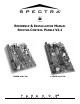
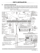
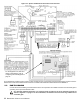
Figure 2.2: Spectra 1728EX and 1728 Control Panel Overview For the keypad’s zone, EOL and tamper configurations, refer to Configuring The LED Keypads on page 14. 2.2 EARTH GROUND Connect the zone and dialer ground terminals from the control panel to the metallic enclosure and cold water pipe or grounding rod as per local electrical codes. For maximum lightning protection, use separate earth grounds for the zone and dialer grounds as shown in Figure 2.1 on page 7.
2.3 AC POWER Do not use any switch-controlled outlets to power the transformer. Connect the transformer as shown in Figure 2.1 on page 7. Use Table 1 to determine the required transformer. Table 1: Transformer Requirements Table Transformer: Amseco XP-1620 16VAC 20VA (Not verified by UL) UL: Basler Electric BE156240CAA007 16.5VAC 40VA Spectra DC Power Supply rated at: 1.2A 1.
2.6 TELEPHONE LINE CONNECTION 2.7 BELL OUTPUT CONNECTION In order to report system events to the central station, you must connect the incoming telephone company wires into the TIP and RING connections of the control panel and then run the wires from T1 and R1 to the telephone or telephone system as shown in Figure 2.1 on page 7. The BELL+ and BELL- terminals power bells, sirens and other warning devices requiring a steady voltage output during an alarm.
2.9 SINGLE ZONE INPUTS Detection devices such as motion detectors and door contacts are connected to the control panel's zone input terminals. Figure 2.5 on page 11 demonstrates single zone input terminal connections recognized by Spectra. Once connected, the associated zone's parameters must be defined. For details refer to Zone Programming on page 19. Figure 2.5: Single Zone Input Connections 2.
Figure 2.6: Double Zone (ATZ) Input Connections 2.11 KEYPAD AND KEYPAD ZONE CONNECTIONS To connect the keypads to the control panel, remove the back cover and wire the GRN, YEL, RED, and BLK terminals of each keypad to the corresponding terminals on the control panel as shown in Figure 2.1 on page 7 or Figure 2.2 on page 8. There is no limit to the number of keypads that can be connected to the control panel so long as the current consumption does not surpass 700mA.
2.12 KEYSWITCH CONNECTIONS Figure 2.8: Keyswitch Keyswitches allow users to arm or disarm a partition by pushing a button or by activating a switch with a key. Connect the keyswitch as shown in Figure 2.8 directly to the control panel terminals. Once a keyswitch is connected, it must be assigned to a zone and its parameters must be programmed (see Zone Programming on page 19 and Keyswitch Options on page 25). 2.
Table 3: Decimal and Hexadecimal Programming Table 3.2.
3.3.1 CONFIGURING THE 1686H, 1686V AND 1689 KEYPADS V2.0 OR HIGHER The keypad’s zone number, EOL definition and tamper switch are programmed through the control panel’s programming mode. To do so: How Do I Configure The Keypad? STEP 1: Press [ENTER] STEP 2: Enter your [INSTALLER CODE] (default: 000000 or 0000) STEP 3: Press the [PG] (1686H/V) / [FNC1] (1689) key and hold it for 3 seconds. STEP 4: Press the desired key ([1] to [3].
J2 - EOL Definition Jumper Jumper J2 determines the keypad zone’s EOL definition. When the jumper is OFF, EOL is disabled and the keypad zone uses the on-board EOL resistor. When the jumper is ON, EOL is enabled and the keypad zone requires that an external EOL resistor be connected (refer to Spectra 1738EX and 1738 Control Panel Overview on page 7 and Spectra 1728EX and 1728 Control Panel Overview on page 8 for more details). J2 OFF - EOL disabled J2 ON - EOL enabled 3.
4.1 ACCESS CODE LENGTH Section [127]: System Options Option [2] OFF = 6-Digit Access Codes Option [2] ON = 4-Digit Access Codes (default) All access codes can be set to lengths of either 4- or 6-digits. When the 4-digit option is selected, entering a 4-digit code will allow access. Using the 6-digit option, entering 6 digits is required to allow access.
4.4.3 BYPASS PROGRAMMING Sections [302] to [348]: User Codes 002 to 048 Option [3] OFF = Bypass Programming Disabled Option [3] ON = Bypass Programming Enabled (default) User codes with this option enabled can perform Bypass Programming in assigned partitions. 4.4.4 STAY ARMING Sections [302] to [348]: User Codes 002 to 048 Option [4] OFF = Stay Arming Disabled Option [4] ON = Stay Arming Enabled for selected User Code (default) User codes with this option enabled can Stay Arm assigned partitions. 4.4.
PART 5: ZONE PROGRAMMING The Spectra control panel’s zone assignment depends on where the detection devices are connected (see Table 4). Table 4: Zone Recognition Table Device connected to which input? 1728/EX 1728 1728/EX 1728 With Re-assign Keypad Zone 2 enabled (p. 19) 1738/EX 1738 1738/EX 1738 With Re-assign Keypad Zone 2 enabled (p.
5.3 REASSIGN ZONES TO EXPANSION INPUTS (1728EX & 1728 ONLY) Section [126]: General Options Option [8] OFF = Reassign Zones to Expansion Inputs Disabled (default) Option [8] ON = Reassign Zones to Expansion Inputs Enabled Reassign Zones to Expansion Inputs changes the zone numbering to increase the number of expansion inputs that can be displayed on 10-Zone LED Keypads.
Figure 5.1: Spectra Zone Programming [001] = Zone 1 [002] = Zone 2 [003] = Zone 3 [004] = Zone 4 [005] = Zone 5 [006] = Zone 6 [007] = Zone 7 [008] = Zone 8 Press the [ENTER] key Enter the [INSTALLER CODE] Zone Definitions 1 - Entry Delay 1 2 - Entry Delay 2 3 - Follow 4 - Instant 5 - 24Hr. Burglary 6 - 24Hr. Buzzer Additional definitions for on-board terminals: 7 - Keyswitch 8 - 24Hr. Fire 9 - 24Hr.
5.5.2 ENTRY DELAY 2 Sections [001] to [016]: Zones 1 to 16, First Digit = 2 Entry Delay 2 zones are identical to the Entry Delay 1 zones (see section 5.5.1), except it uses a separate Entry Delay Timer. To program the Entry Delay 2 Timer, key in the desired 3-digit delay value (000 to 255 seconds, Default = 45 seconds) into section [070]. This timer is also used as the Stay Delay timer (see section 6.2). 5.5.
5.6.2 STANDARD 24HR. FIRE ZONE 1728/EX: Sections [001] to [004]: Zones 1 to 4, First Digit = 8 1738/EX: Sections [001] to [007]: Zones 1 to 7, First Digit = 8 Whenever a Standard 24Hr. Fire Zone opens, whether it is armed or disarmed, the control panel will generate the following: • The control panel can send the corresponding Alarm Report Code from sections [187] to [190].
5.8.1 AUTO ZONE SHUTDOWN Sections [001] to [016] = Zones 1 to 16 Option [1] OFF = Auto Zone Shutdown Disabled Option [1] ON = Auto Zone Shutdown Enabled for selected zone (default) If, in a single armed period, the number of alarms generated by a zone with the Auto Zone Shutdown option enabled exceeds the number defined by the Auto Zone Shutdown Counter, the control panel will no longer generate an alarm for that zone.
5.8.6 DELAY BEFORE ALARM REPORT CODE Sections [001] to [016]: Zones 1 to 16 TRANSMISSION Option [7] OFF = Delay Alarm Transmission Disabled (default) Option [7] ON = Delay Alarm Transmission Enabled for Selected Zone When an alarm condition occurs on a zone with this option enabled, the control panel enables the bell/ siren output, but does not report the alarm to the central station until the end of the Alarm Before Transmission Delay.
Enabling the ATZ feature allows you to install two detection devices per zone input terminal. Each detection device will have its own zone, displaying zone status on the keypad and sending separate alarm codes for each zone. The extra zones are recognized as described in Table 4 on page 19 or in Figure 5-4 below. For more information on how to connect to detection devices, please refer to Double Zone Inputs on page 11.
PART 6: ARMING AND DISARMING OPTIONS 6.1 SWITCH TO STAY ARMING Section [133] = Partition 1, Section [134] = Partition 2 Option [4] OFF = Switch to Stay Arming Disabled (default) Option [4] ON = Switch to Stay Arming Enabled If a user Regular arms a partition, but does not exit through (open and close) an Entry Delay zone during the Exit Delay, the control panel can be programmed to switch from Regular Arming to Stay Arming. 6.
6.6 TIMED AUTO-ARMING Section [133] = Partition 1, [134] = Partition 2 Option [1] OFF = Timed Auto-Arming Disabled (default) Option [1] ON = Timed Auto-Arming Enabled Each partition can be programmed to arm every day at the time specified by the Auto-Arm Timer. The Auto-Arming Options (see section 6.8) determine the partition's arming method. Any open zones detected when a partition is Auto-Armed will be bypassed regardless of their definition (except 24hr. zones).
6.9 ONE-TOUCH ARMING* Section [130]: Options [1] to [4] Option [1] ON = Press & hold the [ENTER] key for One-touch Regular Arming. Option [2] ON = Press & hold the [STAY] key for One-touch Stay Arming. Option [3] ON = Press & hold the [FORCE] key for One-touch Force Arming. Option [4] ON = Press & hold the [BYP] key for One-touch Bypass Programming. The One-touch Arming features allow users to arm the system without having to enter any access codes.
PART 7: ALARM OPTIONS 7.1 BELL CUT-OFF TIMER (5 minutes minimum for CUL installations) Section [073] = Partition 1, [074] = Partition 2 000 = Disabled, 001 to 255 minutes, Default = 4 min. After an audible alarm, the bell or siren will stop upon disarming of the partition or when the Bell Cut-Off Timer has elapsed, whichever comes first. 7.2 RECYCLE ALARM After the Bell Cut-Off Timer and the Recycle Delay have elapsed, the control panel will re-verify the zone status.
Recognition ignores the bypass definition. This means the control panel will generate an incident as per Tamper Recognition settings if a tamper or wire fault occurs on a bypassed zone. 7.4 KEYPAD PANIC OPTIONS Section [128]: General Options Option [1] OFF = Emergency Panic Disabled (default) Option [1] ON = Emergency Panic Enabled Pressing the [1] and [3] keys simultaneously on the keypad for 2 seconds will generate a silent or audible alarm as defined by option [4].
PART 8: REPORTING AND DIALER SETTINGS The following section explains all the features and options that must be programmed in order for your security system to properly report system events to a central station. When an event (e.g. zone in alarm) occurs in the system, the control panel verifies if a report code was programmed in the section corresponding to the event (except Ademco Contact ID “All Codes”).
8.1 REPORTING/DIALER (ENABLE/DISABLE) 8.2 REPORT CODES Section [135]: Dialer Options Option [3] OFF = Reporting/Dialer Disabled (default) Option [3] ON = Reporting/Dialer Enabled A report code is a 1- or 2-digit hexadecimal value consisting of digits from 1 to F. Each section from [160] to [213] represents a set of up to four specific events and each of these events can be programmed with a separate 1- or 2digit report code.
8.2.4 SPECIAL DISARMING Section [186] REPORT CODES Whenever using one of the special disarming features, the control panel can send the report code to the central station, identifying how the system was disarmed. • CANCEL AUTO-ARM: A partition is disarmed during the Timed Auto-Arm's 60-second Exit Delay (see page 28). Only reports if Disarming Reporting Options (see page 40) are set to always report disarming. • REMOTE DISARM: System is disarmed using the Winload software.
8.2.10 SYSTEM TROUBLE REPORT CODES Section [205] to [207] Whenever the system generates one of the instances listed below, the control panel can send the appropriate report code to the central station identifying the type of system trouble. Section [205] • Future use • AC FAILURE: The control panel has detected a loss of AC power. Transmission of this report code can be delayed (see Power Failure Report Delay on page 39). • BATTERY FAILURE: backup battery is disconnected or battery voltage is ≤10.5V.
8.3 CENTRAL STATION TELEPHONE NUMBERS Section [151] = Phone#1, [152] = Phone#2, [153] = Backup Phone#: Up to 32 digits The Spectra Control Panels can dial up to 2 different central station telephone numbers. You can enter any digit from 0 to 9 and any special keys or functions (see Table 7) up to a maximum of 32 digits. For more information on how these telephone numbers are used, please refer to Event Call Direction on page 38 and Reporting Formats in section 8.5.
8.5.2 ADEMCO EXPRESS The Ademco Express is a high-speed reporting format, which will transmit the 2-digit (11 to FF) report codes programmed into sections [160] to [213]. Unlike other Ademco formats, the Ademco Express does not use the Contact ID Report Codes. 8.5.3 ADEMCO CONTACT ID Ademco Contact ID is a fast communicator format that uses tone reporting instead of pulse reporting.
8.7 EVENT CALL DIRECTION This feature determines where each group of events will be reported. The control panel events are divided into five groups (see above) where each event group can be programmed to dial one or both Central Station Telephone Numbers. When a reportable event occurs in the system, the control panel will verify that one of the two telephone numbers has been enabled. The control panel will begin by dialing the selected telephone number(s).
Option [5] ON = Dialer will hang-up if no dial tone is present after 16 seconds 8.12 MAXIMUM DIALING ATTEMPTS Section [081] 001 to 016 attempts, Default = 8 attempts The value programmed in section [081] determines how many times the control panel will re-dial the same Central Station Telephone Number before proceeding to the next number. 8.
8.18 DISARM REPORTING OPTIONS Section [131]: Arming /Disarming Options Option [1] OFF = Always Report Disarming Option [1] ON = Report Disarming Only After Alarm (default) With option [1] off, the control panel will send the Disarming report codes (see page 33) to the central station every time the system is disarmed. With option [1] on, the control panel will send the Disarming report codes to the central station when the system is disarmed following an alarm. 8.
PART 9: PROGRAMMABLE OUTPUTS A PGM is a programmable output that toggles to its opposite state (i.e. a normally open PGM will close) when a specific event has occurred in the system. For example, a PGM can be used to reset smoke detectors, activate bells or strobe lights, open/ close garage doors and much more. When a PGM closes, the control panel supplies a ground to the PGM activating any device or relay connected to it.
9.3 PGM DELAY Section [066] = PGM1, [067] = PGM2, [068] = Global PGM 001 to 255 seconds, 000 = Follows Deactivation Event, Default = 5 seconds Instead of deactivating the PGM on the occurrence of a specific event, the PGM will deactivate after the period programmed here has elapsed. PGM2 is available on the 1738EX and 1738 only. If a PGM Delay is programmed, the deactivation event can be used as a second activation event. 9.
PART 10: SYSTEM SETTINGS 10.1 HARDWARE RESET Performing a hardware reset will set all control panel settings to factory default except for the Panel ID and PC Password. Also, the event buffer will not be erased. To perform a power down reset: 1) Make sure the Installer Lock is disabled (see below) 2) Remove battery and AC power from the control panel. 3) Set the RESET jumper to on by placing a jumper on the RESET pins of the control panel. 4) Re-connect AC and battery power to the control panel.
10.6 SYSTEM REAL-TIME CLOCK Section [280] Program the current time into section [280] using the 24-hour clock (i.e. 8:30PM = 20:30). 10.7 CLOCK ADJUST Section [088] 000 = Disabled, 001 to 255, Default = Disabled 001 to 127 = + 1 to +127 seconds 128 to 255 = -1 to -127 seconds If you notice a gain or loss in control panel time, calculate the average gain or loss per day and program the opposite amount in order to automatically correct the time setting every 24 hours.
10.
10.13 PRINTER BUS MODULE SUPERVISION Section [129]: General Options Option [8] OFF = Printer Bus Module Supervision Disabled (default) Option [8] ON = Printer Bus Module Supervision Enabled By enabling this option, the control panel will supervise the Printer Bus Module (APR3-PRT1) connected to the Spectra bus.
[7] OFF / [8] ON: Trouble Only When a tamper occurs on a wireless transmitter zone in a disarmed system, a Wireless Transmitter Supervision Loss will appear in the keypads’ Trouble Display (see page 50) and the control panel will attempt to transmit the TX Supervision Loss report code programmed in section [213]. When it occurs on in an armed system, the control panel will follow the zone's Alarm Types setting (see page 24).
PART 11: SETTINGS FOR WINLOAD SOFTWARE 11.1 PANEL ANSWER OPTIONS The following two options define how the control panel answers an incoming call from a computer using the WinLoad Software for Windows®. 11.1.1 ANSWERING MACHINE OVERRIDE Section [077] 000 = Disabled, 010 to 255 seconds, Default = disabled When using the WinLoad software to communicate remotely with an installation site that uses an answering machine or service, the answering machine override must be programmed.
11.5 CALL WINLOAD SOFTWARE [ENTER] + [INSTALLER CODE] + [BYP] The control panel will dial the PC Telephone Number programmed in section [150] in order to communicate with the WinLoad software. The control panel and the WinLoad software will verify that the Panel Identifier and the PC Password match before establishing communication. 11.
PART 12: USER OPERATION 12.1 TROUBLE DISPLAY The Spectra system continuously monitors fourteen possible trouble conditions. When a trouble condition occurs, the [TBL] key or [TRBL] indicator will illuminate on the LED keypads or “Trouble” will appear on the LCD keypad’s screen. Press the [TBL] or [TRBL] key to switch to the Trouble Display.
Table 10: Trouble List LED # Description Telephone Line Monitoring [10] [STAY] or Fire Loop Trouble [11] Keypad Fault [FORCE] or [16] [BYP] or [12] [MEM] or [13] Module Loss Wireless Transmitter Supervision Loss Details If the Telephone Line Monitoring (TLM) feature is enabled (see section [135]), this trouble indicates that the control panel has not detected the presence of a telephone line for 30 seconds. Indicates a wiring problem on a Fire Zone.
12.3 DISARMING & DEACTIVATING AN ALARM To disarm an already armed system or to deactivate an alarm, simply key in a valid access code. Program a designated entry/exit point, such as the front door or the garage door with an Entry Delay Timer. When these entry/ exit point are opened (breached), it will set off a timer. The system will not generate an alarm until this timer elapses, giving users enough time to enter the premises and disarm the system.
12.7 FORCE ARMING** Force Arming allows users to rapidly arm the system, without having to wait for all zones in the system to be closed. Force Arming is commonly used when a motion detector is protecting the area occupied by a keypad. Therefore, when arming the system, if the motion detector is set as a Force Zone, the control panel will ignore the zone and allow users to arm the system even if the zone is open.
12.9 ONE-TOUCH ARMING One-Touch Arming allows users to arm the system without using an access code. Simply press and hold a key. OneTouch Arming can be used to allow specific individuals like service personnel (i.e. cleaners, maintenance) to arm the system when leaving the protected area, without giving them access to any other alarm system operations. One-Touch Regular Arming Press and hold the [ENTER] key for 3 seconds* to arm all zones in the partition.
12.14 PROGRAMMING CHIME ZONES Users can program which zones will be Chime Enabled. A Chime Enabled zone will cause the keypad to emit a rapid intermittent beep tone (BEEP-BEEP-BEEP-BEEP) advising the user every time it is opened. Each keypad must be Chime Programmed separately. 10-ZONE LED KEYPAD: Press and hold any key from [1] to [10] for 3 seconds to activate or deactivate Chiming for zones 1 to 10. For example, press and hold the [1] key to enable chiming on zone 1.
FCC WARNINGS IMPORTANT INFORMATION This equipment complies with Part 68 of the FCC rules subpart D and CS03. Inside the cover of this equipment is a label that contains, among other information, the FCC registration number of this equipment. NOTIFICATION TO TELEPHONE COMPANY Upon request, customer shall notify telephone company of particular line to which the connection will be made, and provide the FCC registration number and the ringer equivalence of the protective circuit.
used by the device, to prevent overloading. The termination on a loop may consist of any combination of devices subject only to the requirement that the total of the Load Numbers of all of the devices does not exceed 100. Industry Canada certification is only applicable to installation of devices which include transformers approved by the Canadian Standards Association (CSA). RESTRICTIONS CONCERNANT LE RACCORDEMENT DE MATÉRIEL L'étiquette d'Industrie Canada identifie le matériel homologué.
INDEX Numerics 24Hr. Buzzer Zone 22 24Hr. Delayed Fire Zone 23 24Hr.
K Key.
User Code Options 17 User Operation 50 W Winload Software 13 Wireless Bus Module Supervision 46 Wireless Transmitter Low Battery Supervision 46 Wireless Transmitter Supervision Options 46 Z Zone Alarm Report Codes 34 Zone Alarm Restore Report Codes 34 Zone Doubling 25 Zone Options 23 Zone Partition Assignment 23 Zone Programming 19 Zone Restore Report Options 40 Zone Speed 25 Zone Tamper Report Codes 34 Zone Tamper Restore Report Codes 34 60 REFERENCE & INSTALLATION MANUAL
780 boul. Industriel, St. Eustache, Montréal, Québec J7R 5V3 Fax: (450) 491-2313 www.paradox.