
Installation Instructions


3 | Pag
e
Mountin
Plan yo
u
at leas
t
buildin
g
source/
b
If long
cables
s
improve
d
vegetat
i
To moun
t
the bra
c
front o
f
mountin
g
into th
r
router
b
The too
l
The rou
t
provide
shielde
d
the Eth
e
Secure
t
used to
interna
l
Remove
t
Replace
Antenna
Install
a
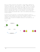
There a
r
coded r
i
that id
e
1 of th
e
router.
Install
For bes
t
pole po
i
To moun
t
e
g the rou
t
u
r install.
t
3 meters
h
g
, vegetati
b
ackhaul sh
range dire
s
hould be k
d
by increa
i
on, and cu
r
t
your rout
c
ket and ha
r
f
the brack
g
. Mount th
r
ee slots o
n
b
y insertin
l
provided
t
er has bee
n
internet t
d
ethernet
e
rnet conne
t
he Etherne
provide ba
l
ethernet
p
t
he pigtail
cover.
connecti
o
a
tion shoul
r
e six fema
i
ngs around
e
ntifies th
e
5GHz rout
the two om
n
t
performan
i
nting towa
r
t
the anten
n
t
er:
Ideally t
h
h
igh and a
b
o
n, hills
o
o
uld be wi
t
ctional an
t
ept to a m
i
sing the h
e
r
vature of
er, secure
l
r
dware. Th
e
et should
b
e router t
o
n
the rout
e
g the lock
i
is used to
n
shipped
w
o
a comput
e
cable and
p
ctor to se
c
t cable ev
e
ckhaul to
t
p
igtail wi
l
from this
o
ns:
d be perfo
r
le N-type
c
the conne
c
e 2.4GHz A
P
er. The ot
h
n
idirectio
n
ce, secure
l
r
ds the lo
c
n
a, place
t
h
e router s
b
ove any p
o
o
r other ob
t
hin maxim
u
t
ennas are
i
nimum. (L
o
e
ight of t
h
the earth.
l
y mount t
h
e
three fi
n
b
e kept cle
o
the brac
k
e
r. The co
r
i
ng screw
p
secure thi
w
ith the e
x
e
r or switc
p
lug it int
c
ure the c
a
e
ry two to
t
he router.
l
l be conne
port and
r
r
med by a
q
c
onnectors
c
tor for t
h
P
. There a
r
h
er two co
n
n
al antenn
a
l
y install
c
ation of
a
t
he short s
hould be m
o
o
tential in
t
jects. A p
o
u
m distance
planned to
o
ng range d
i
h
e router.
T
)
h
e bracket
t
n
gers of th
e
ar as this
k
et. The th
r
r
d grip sho
u
p
in to the
b
s pin scre
w
x
ternal Eth
e
h from the
o the rout
e
a
ble and to
three mete
r
Remove th
e
cted to th
e
r
econnect i
t
q
ualified p
r
used to co
n
h
e bands us
e
r
e two pink
n
nectors ar
e
a
e to the t
w
one direct
i
a
nother rou
t
ide of the
o
unted out
d
t
erference
o
wer
of 100 me
t
be used,
t
i
stance ca
n
T
his is to
t
o the mou
n
e
bracket
s
would int
e
r
ee finger
s
u
ld be fac
i
b
ottom of
t
w
.
e
rnet conn
e
router. R
o
e
r. Tighte
n
make a we
a
r
s to the
p
e
cover wi
t
e
unmarked
t
to the p
o
r
ofessiona
l
n
nect the
a
e
d. There
a
connector
s
e
green fo
r
w
o yellow
c
i
onal 15dB
i
t
er in the
L-bracket
d
oors
of
t
ers.
t
he RF
n
be
clear buil
n
ting pole
u
s
hould be f
a
e
rfere with
s
of the br
a
i
ng down. S
t
he router
e
ctor confi
o
ute the co
r
n
down the
a
therproof
p
ole. The r
o
t
h the tool
port or ma
r
o
rt marked
l
.
a
ntennae. T
h
a
re two yel
s
that are
u
r
radio2 of
c
onnectors.
i
panel ant
router pro
on the fou
r
dings,
u
sing the
u
a
cing up.
T
the route
r
a
cket will
ecure the
to the bra
c
gured to
r
d grip on
cord grip
t
connection.
o
uter may
b
provided.
r
ked “LAN.
“WAN.”
h
ey have c
o
low connec
t
u
sed for r
a
the 5GHz
enna on th
e
viding bac
k
r
studs on
u
sing
T
he
r
fit
c
ket.
a
t
o
b
e
The
”
o
lor
t
ors
a
dio
e
k
haul.
the