
Owner manual


SharpEye
TM
UV Flame Detector User Guide
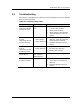
44 Outputs
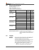
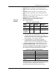
A.2 Electrical Specifications
Operating Voltage:18-32 VDC
Power Consumption: Table 19
Table 19: Electrical Specifications
Operating
Voltage
Status
All
Outputs
Without
0-20mA
Power
Consumption
(Max. 24VDC)
Normal
1.61W
1.56W
Normal when Heater On
2.28W
2.16W
Alarm
2.64W
2.28W
Alarm when Heater On
3.24W
2.88W
Maximum Current
(Max. 24VDC)
Normal
70mA
65mA
Normal when Heater On
95mA
90mA
Alarm
110mA
95mA
Alarm when Heater On
135mA
120mA
Power
Consumption
(Max. 18-32VDC)
Normal
1.95W
1.85W
Normal when Heater On
2.56W
2.45W
Alarm
3.04W
2.56W
Alarm when Heater On
3.68W
3.2W
Maximum Current
(18-32VDC)
Normal
90mA
85mA
Normal when Heater On
105mA
100mA
Alarm
130mA
115mA
Alarm when Heater On
160mA
145mA
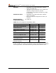
Electrical Input Protection
The input circuit is protected against
voltage-reversed polarity, voltage transients,
surges and spikes according to MIL-STD-
1275B
A.3 Outputs
Electrical
Interface
There are five output-wiring options. These options must
be defined at the factory per the customer order and
cannot be changed at the customer facility.
See General Instructions for Electrical Wiring on page 49
for the wiring/terminal diagram for each option.
Unless otherwise specified, the default is Option 1. The
wiring arrangement is identified on the detector by the
part number (see Model and Types on page 2).
Option 1: Power, RS-485, 0-20mA (Sink), Fault I
Relay (N.C), Alarm Relay, (N.O) (see Figure 7).