
Owner manual


TM 40/40U, Rev (7) July 2013
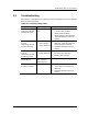
Troubleshooting 45
Option 2: Power, RS-485, 0-20mA (Source) and
HART protocol, Fault Relay (N.O), Alarm Relay, (N.O),
(N.C).
Option 3: Power, RS-485, 0-20mA (Source) and
HART protocol, Fault Relay (N.O), Alarm Relay (N.O,
N.C).
Option 4: Power, RS-485, Fault Relay (N.C), Auxiliary
Relay (N.O), Alarm Relay, (N.O).
Option 5: Power, RS-485, Fault Relay (N.O),
Auxiliary Relay (N.O), Alarm Relay, (N.O).
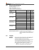
Electrical
Outputs
Dry Contact Relays
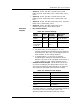
Table 20: Contact Ratings
Relay
Name
Type
Normal
Position
Maximum
Ratings
Alarm
SPDT
N.O., N.C.
2A at 30 VDC
Auxiliary
SPST
N.O.
2A at 30 VDC
Fault
(see Notes
1 and 2)
SPST
N.C. or
N.O
2A at 30 VDC
Notes:
1. The Fault relay (in wiring options 1, 2, 4) is
normally energized closed during normal operation
of the detector. The relay is de-energized open if a
fault condition or low voltage situation.
2. In wiring options 3, 5 the relay is normally
energized open during normal operation of the
detector. The relay is de-energized close contact if
a fault condition or low voltage situation occurs.
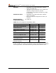
0-20mA Current Output: The 0-20mA can be Sink
or Source according to the wiring option source (see
General Instructions for Electrical Wiring on page 49).
The maximum permitted load resistance is 600Ω.
Table 21: 20 mA Current Output
State
Output
Fault
0 +1 mA
BIT Fault
2 mA±10%
Normal
4 mA±10%
Warning
16 mA±5%
Alarm
20 mA±5%
HART Protocol
The HART protocol is a digital communication signal at
a low level on top of the 0-20mA. This is a bi-
directional field communication protocol used to