MC.31xx fast 12 bit transient recorder, A/D converter board for CompactPCI bus Hardware Manual Software Driver Manual English version April 27, 2006 SPECTRUM SYSTEMENTWICKLUNG MICROELECTRONIC GMBH · AHRENSFELDER WEG 13-17 · 22927 GROSSHANSDORF · GERMANY PHONE: +49 (0)4102-6956-0 · FAX: +49 (0)4102-6956-66 · E-MAIL: info@spec.de · INTERNET: http://www.spectrum-instrumentation.
(c) SPECTRUM SYSTEMENTWICKLUNG MICROELECTRONIC GMBH AHRENSFELDER WEG 13-17, 22927 GROSSHANSDORF, GERMANY SBench is a registered trademark of Spectrum Systementwicklung Microelectronic GmbH. Microsoft, Visual C++, Visual Basic, Windows, Windows 98, Windows NT, Window 2000 and Windows XP are trademarks/registered trademarks of Microsoft Corporation. LabVIEW, DASYLab, Diadem and LabWindows/CVI are trademarks/registered trademarks of National Instruments Corporation.
Introduction....................................................................................................................... 6 Preface ............................................................................................................................................................................... 6 General Information .............................................................................................................................................................
Programming the Board .................................................................................................. 36 Overview .......................................................................................................................................................................... Register tables ................................................................................................................................................................... Programming examples........
Option Multiple Recording ............................................................................................... 77 Recording modes ............................................................................................................................................................... Standard Mode............................................................................................................................................................ FIFO Mode ...............................
Preface Introduction Introduction Preface This manual provides detailed information on the hardware features of your Spectrum instrumentation board. This information includes technical data, specifications, block diagram and a connector description. In addition, this guide takes you through the process of installing your board and also describes the installation of the delivered driver package for each operating system.
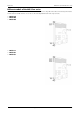
Introduction Different models of the MC.31xx series Different models of the MC.31xx series The following overview shows the different available models of the MC.31xx series. They differ in the number of mounted acquisition modules and the number of available channels. You can also see the model dependant allocation of the input connectors. • MC.3110 • MC.3120 • MC.3130 • MC.3111 • MC.3121 • MC.
Different models of the MC.31xx series Introduction • MC.3112 • MC.3122 • MC.3132 8 MC.
Introduction Additional options Additional options Digital inputs This option allows the user to acquire additional digital channels synchronous and phase-stable along with the analog data. Therefore the analog data is filled up with the digital bits up to 16 Bit data width. This leads to a possibility of acquiring 4 additional digital bits per channel with 12 bit resolution boards, and 2 additional digital bits per channel with 14 bit resolution boards.
Additional options Introduction Starhub The star hub module allows the synchronisation of up to 16 MC boards. It is possible to synchronise boards of the same type with each other as well as different types. The module acts as a star hub for clock and trigger signals. Each board is connected with a small cable of the same length, even the master board. That minimises the clock skew between the different boards.
Introduction The Spectrum type plate The Spectrum type plate The Spectrum type plate, which consists of the following components, can be found on all of our boards. The board type, consisting of the two letters describing the bus (in this case MC for the CompactPCI bus) and the model number. The size of the on-board installed memory in MSamples. In this example there are 8 MS (16 MByte) installed. The serial number of your Spectrum board. Every board has a unique serial number.
Hardware information Introduction Hardware information Block diagram Technical Data Resolution Differential linearity error Integral linearity error Multi: Trigger to 1st sample delay Multi: Recovery time ext. Trigger accuracy int. Trigger accuracy Ext. clock: delay to internal clock input signal with 50 ohm termination Digital Inputs input impedance Digital Inputs delay to analog sample Min internal clock Min external clock 12 bit ≤ 1 LSB (ADC) ≤ 2.
Introduction Hardware information Dynamic Parameters Test - Samplerate Testsignal frequency SNR (typ) THD (typ) SFDR (typ), excl harm. SINAD (typ) ENOB (based on SINAD) MC.3110 MC.3111 1 MS/s 90 kHz > 67.5 dB < -62.8 dB > 80.8 dB > 61.5 dB > 9.9 LSB MC.3112 MC.3120 MC.3121 10 MS/s 1 MHz > 64.9 dB < -62.5 dB > 80.5 dB > 60.5 dB > 9.8 LSB 1 MS/s 90 kHz > 66.9 dB < -62.8 dB > 80.5 dB > 61.4 dB > 9.9 LSB MC.3122 10 MS/s 1 MHz > 64.9 dB < -62.5 dB > 78.5 dB > 60.5 dB > 9.8 LSB MC.3130 MC.
System Requirements Hardware Installation Hardware Installation System Requirements All Spectrum MC.xxxx instrumentation boards are compliant to the CompactPCI 6U standard and require in general one free slot. Depending on the installed options additional free slots can be necessary. Warnings ESD Precautions The boards of the MC.xxxx series contain electronic components that can be damaged by electrostatic discharge (ESD).
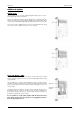
Hardware Installation Installing the board in the system Installing a board with digital inputs/outputs The locks on the top and bottom side of both CompactPCI brackets need to be unlocked and opened before installing the board into a free slot of the system. Therefore you need to press the little buttons on the inside of the fasteners and move them outwards (see figure). Now slowly insert the card into the host system using the key ways until both locks snap in with a „click“.
Installing the board in the system Hardware Installation Installing multiple boards synchronized by starhub Hooking up the boards Before mounting several synchronized boards for a multi channel system into the chassis you have to hook up the boards with their synchronization cables first. Spectrum ships the boards together with the needed amount of synchronization cables. All of them are matched to the same length, to achieve a zero clock delay between the boards. Only use the included flat ribbon cables.
Hardware Installation Installing the board in the system Installing multiple synchronized boards Hooking up the boards Before mounting several synchronized boards for a multi channel system into the chassis you have to hook up the boards with their syncronization cables first. Spectrum ships the boards together with the needed synchronization cable. All of the possible four boards must be wired with delivered synchronization cable. The figure is showing that exemplarily for three synchronized boards.
Interrupt Sharing Software Driver Installation Software Driver Installation Before using the board a driver must be installed that matches the operating system. The installation is done in different ways depending on the used operating system. The driver that is on CD supports all boards of the MI, MC and MX series. That means that you can use the same driver for all boards of theses families. Interrupt Sharing This board uses a PCI interrupt for DMA data transfer and for controlling the FIFO mode.
Software Driver Installation Windows 98 Windows 98 Installation When installing the board in a Windows 98 system the Spectrum board will be recognized automatically on the next start-up. The system offers the direct installation of a driver for the board. Let Windows search automatically for the best driver for your system. Select the CD that was delivered with the board as installation source. The driver files are located on CD in the directory \Driver\Win98_2k_XP.
Windows 98 Software Driver Installation After clicking the driver info button the detailed version information of the driver is shown. In the case of a support question this information must be presented together with the board’s serial number to the support team to help finding a fast solution. Driver - Update If a new driver version is to be installed no Spectrum board should be in use. So please stop and exit all software that could access the boards. New drivers are available at http://www.
Software Driver Installation Windows 2000 Windows 2000 Installation When installing the board in a Windows 2000 system the Spectrum board will be recognized automatically on the next start-up. The system offers the direct installation of a driver for the board. Let Windows search automatically for the best driver for your system. Select the CD that was delivered with the board as installation source. The driver files are located on CD in the directory \Driver\Win98_2k_XP.
Windows 2000 Software Driver Installation Driver - Update If a new driver version should be installed no Spectrum board is allowed to be in use by any software. So please stop and exit all software that could access the boards. A new driver version is directly installed from the device manager. Therefore please open the properties page of the driver as shown in the section before.
Software Driver Installation Windows XP Windows XP Installation When installing the board in a Windows XP system the Spectrum board will be recognized automatically on the next start-up. The system offers the direct installation of a driver for the board. Do not let Windows automatically search for the best driver, because sometimes the driver will not be found on the CD. Please take the option of choosing a manual installation path instead.
Windows XP Software Driver Installation On the property page Windows XP shows the date and the version of the installed driver. After clicking the driver details button the detailed version information of the driver is shown. In the case of a support question this information must be presented together with the board’s serial number to the support team to help finding a fast solution. Driver - Update If a new driver version should be installed no Spectrum board is allowed to be in use by any software.
Software Driver Installation Windows NT Windows NT Installation Under Windows NT the Spectrum driver must be installed manually. The driver is found on CD in the directory \Install\WinNTDrv. Please start the „Setup.exe“ program. The installation is performed totally automatically, simply click on the „Next“ button. After installtion the system must be rebooted once (see picture on the right side). The driver is install to support one PCI/PXI or CompactPCI device.
Linux Software Driver Installation Linux Overview The Spectrum boards are delivered with drivers for linux. It is necessary to install them manually following the steps explained afterwards. The linux drivers can be found on CD in the directory /Driver/linux. As linux is an open source operating system there are several distributions in use world-wide that are compiled with different kernel settings.
Software Driver Installation Linux Installing the device You connect a device to the driver with the mknod command. The major number is the number of the driver as shown in the last step, the minor number is the index of the board starting with 0. This step must only be done once for the system where the boards are installed in. The device will remain in the file structure even if the board is de-installed from the system.
Software Overview Software Software This chapter gives you an overview about the structure of the drivers and the software, where to find and how to use the examples. It detailed shows how the drivers are included under different programming languages and where the differences are when calling the driver functions from different programming languages. This manual only shows the use of the standard driver API.
Software C/C++ Driver Interface C/C++ Driver Interface C/C++ is the main programming language for which the drivers have been build up. Therefore the interface to C/C++ is the best match. All the small examples of the manual showing different parts of the hardware programming are done with C. Header files The basic task before using the driver is to include the header files that are delivered on CD together with the board. The header files are found in the directory /Driver/header_c.
C/C++ Driver Interface Software Examples Examples can be found on CD in the path /Examples/linux. There is one subdirectory for each board family. You’ll find board specific examples for that family there. The examples are bus type independent. As a result that means that the MI30xx directory contains examples for the MI.30xx, the MC.30xx and the MX.30xx families. The examples are simple one file programs and can be compiled using the Gnu C compiler gcc. It’s not necessary to use a makefile for them.
Software C/C++ Driver Interface Using the Driver under Linux: hDrv = open ("/dev/spc0", O_RDWR); ... close (hDrv); Function SpcSetParam All hardware settings are based on software registers that can be set by the function SpcSetParam. This function sets a register to a defined value or executes a command. The board must first be initialized. The available software registers for the driver are listed in the board specific part of the documentation below.
Delphi (Pascal) Programming Interface Software Function SpcGetData int16 SpcGetData (int16 nr, int16 ch, int32 start, int32 len, dataptr data); Under Linux the additional parameter nBytesPerSample must be used for this function. For all boards with 8 bit resolution the parameter is „1“, for all boards with 12, 14 or 16 bit resolution this parameter has to be „2“, when reading timestamps this parameter has to be „8“.
Software Delphi (Pascal) Programming Interface The value „nr“ contains the index of the board that you want to access, the value „reg“ is the register that has to be changed and the value „value“ is the new value that should be set to this software register. The function will return an error value in case of malfunction. Function SpcGetParam The function SpcGetParam reads out software registers or status information. The board must first be initialized.
Visual Basic Programming Interface Software Visual Basic Programming Interface The Spectrum boards can be used together with Microsoft Visual Basic as well as with Microsoft Visual Basic for Applications. This allows per example the direct access of the hardware from within Microsoft Excel. The interface between the programming language and the driver is the same for both.
Software Visual Basic Programming Interface Function SpcGetParam The function SpcGetParam reads out software registers or status information. The board must first be initialized. The available software registers for the driver are listed in the board specific part of the documentation below.
Overview Programming the Board Programming the Board Overview The following chapters show you in detail how to program the different aspects of the board. For every topic there’s a small example. For the examples we focussed on Visual C++. However as shown in the last chapter the differences in programming the board under different programming languages are marginal. This manual describes the programming of the whole hardware family. Some of the topics are similar for all board versions.
Programming the Board Initialization This means as a result that it is not necessary to check each driver call for an error but to check for an error before the board is started to see whether all settings have been valid. By reading all the error information one can easily examine where the error occured. The following table shows all the error related registers that can be read out. Register Value Direction Description SPC_LASTERRORCODE 999999 r Error code of the last error that occured.
Initialization Programming the Board Hardware version Since all of the MI, MC and MX boards from Spectrum are modular boards, they consist of one base board and one or two (only PCI and CompactPCI) piggy-back modules. This register SPC_PCIVERSION gives information about the revision of either the base board and the modules. Normally you do not need this information but if you have a support question, please provide the revision together with it.
Programming the Board Initialization PCIBIT_STARHUB 2048 Is set on the board, that carrys the starhub piggy-back module. This flag is set in addition to the PCIBIT_SYNC flag mentioned above. If on no synchronized board the starhub option is installed, the boards are synchronized with the cascading option. PCIBIT_XIO 8192 Is set if the Option Extra I/O is installed. The following example demonstrates how to read out the information about one feature.
Powerdown and reset Programming the Board Example program for the board initialization The following example is only an exerpt to give you an idea on how easy it is to initialize a Spectrum board.
Analog Inputs Channel Selection Analog Inputs Channel Selection One key setting that influences all other possible settings is the channel enable register. An unique feature of the Spectrum boards is the possibility to program the number of channels you want to use. All on-board memory can then be used by these activated channels. This description shows you the channel enable register for the complete board family.
Channel rerouting Analog Inputs Channel rerouting If you only use one or half of the available channels per module enabled, you can route the input connectors to the acquisition channels differently. Normally connector channel 0 is routed to the acquisition channel 0. If you just need for example one channel it might be usefull to record just the signal connected for example to connector channel 2.
Analog Inputs Setting up the inputs Setting up the inputs Input ranges This analog acquisition board uses separate input amplifiers and converters on each channel. This gives you the possibility to set up the desired and concerning your application best suiting input range also separately for each channel. The input ranges can easily be set by the corresponding input registers. The table below shows the available input registers and possible standard ranges for your type of board.
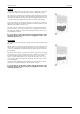
Setting up the inputs Analog Inputs Input offset In most cases the external signals will not be symmetrically related to ground. If you want to acquire such asymmetrical signals, it is possible to use the smallest input range that matches the biggest absolute signal amplitude without exceeding the range. The figure at the right shows this possibility. But in this example you would leave half of the possible resolution unused.
Analog Inputs Setting up the inputs to the input range of ± 1.0 V. After that the four offset settings are set exactely as the offsets to be compensated, but with the the opposite sign. The result is, that all four channels match perfectely to the choosen input range.
Setting up the inputs Analog Inputs of sets available for storing user offset settings depends on the type of board you use. The table below shows all the EEPROM sets, that are available for your board. Register Value Direction Description SPC_ADJ_LOAD 50000 w Loads the specified set of settings from the EEPROM. The default settings are automatically loaded, when the driver is started. r Reads out, what kind of settings have been loaded last.
Standard acquisition modes General Information Standard acquisition modes General Information The standard mode is the easiest and mostly used mode to acquire analog data with a Spectrum A/D board. In standard recording mode the board is working totally independant from the host system (in most cases a standard PC), after the board setup is done. The advantage of the Spectrum boards is that regardless to the system usage the board will sample with equidistant time intervals.
Programming Standard acquisition modes ch7 3132 3140 ch6 3131 ch5 3130 ch4 3122 ch3 3121 ch2 3120 ch1 3112 x x x x x x 3111 ch0 3110 Maximum posttrigger in MSamples x 128 64 n.a. n.a. n.a. n.a. 128 64 n.a. n.a. 32 n.a. 128 64 128 64 32 32 128 64 n.a. n.a. n.a. n.a. 128 64 n.a. n.a. 32 n.a. 128 64 128 64 32 32 128 64 n.a. n.a. n.a. n.a. 128 64 n.a. n.a. 32 n.a. 128 64 128 64 32 32 128 64 n.a. n.a. n.a. n.a.
Standard acquisition modes Programming Status register Register Value Direction Description SPC_STATUS 10 r Status register, of the board. 0 Indicates that the board has been started and is waiting for a triggerevent. SPC_RUN SPC_TRIGGER 10 Indicates that the board is running and a triggerevent has been detected. SPC_READY 20 Indicates, that the board has stopped.
Programming Standard acquisition modes Data organization Normal mode This chapter shows the data organization for all acquisitions that are done with the normal data width of 12 bit. The data organization for the fast 8 bit mode is described in the next passage. In standard mode tha data is organized on the board in two memory channels, named memory channel 0 and memory channel 1. The data in memory is organized depending on the used channels and the type of board.
Standard acquisition modes Programming If the fast 8 bit mode is used the upper byte of the memory word is used to store one channel and the lower byte is used to store another channel. Data must be read out in the normal way from channel 0 (containing 8 bit data of ch0+ch1), channel 1 (ch2+ch3), channel 4 (ch4+ch5) and channel 5 (ch6+ch7) as described above and split into the two 8 bit channels in software afterwards.
Programming Standard acquisition modes Example for SpcGetData, no memory allocation error checking performed: for (i = 0; i < 2; i++) pnData[i] = (ptr16) malloc (lMemsize * lBytesPerSample); // both memory channels have been used // allocate memory for the data pointers // with the maximum size (lMemsize) SpcGetData (hDrv, 0, 0, lMemsize, (dataptr) pnData[0]); SpcGetData (hDrv, 1, 0, lMemsize, (dataptr) pnData[1]); // no demultiplexing is necessary on channel 0 // neither it is on channel 1 If you use
FIFO Mode Overview FIFO Mode Overview General Information The FIFO mode allows to record data continuously and transfer it online to the PC (acquisition boards) or allows to write data continuously from the PC to the board (generation boards). Therefore the on-board memory of the board is used as a continuous buffer.
Programming 1 2 4 8 Channel Channels Channels Channels FIFO Mode Theoretical maximum sample rate 50 MS/s 25 MS/s 12.5 MS/s 6.25 MS/s PCI Bus Throughput [1 Channel] x [2 Bytes per sample] * 50 MS/s = 100 MB/s [2 Channels] x [2 Bytes per sample] * 25 MS/s = 100 MB/s [4 Channels] x [2 Bytes per sample] * 12.5 MS/s = 100 MB/s [8 Channels] x [2 Bytes per sample] * 6.
FIFO Mode Programming Analog acquisition or generation boards 1 2 4 8 Channel Channels Channels Channels Buffer length to be programmed in Bytes 12 bit resolution 14 bit resolution 1 x 2 x [Samples in Buffer] 1 x 2 x [Samples in Buffer] 2 x 2 x [Samples in Buffer] 2 x 2 x [Samples in Buffer] 4 x 2 x [Samples in Buffer] 4 x 2 x [Samples in Buffer] 8 x 2 x [Samples in Buffer] 8 x 2 x [Samples in Buffer] 8 bit resolution 1 x [Samples in Buffer] 2 x [Samples in Buffer] 4 x [Samples in Buffer] 8 x [Samples
Programming FIFO Mode FIFO mode In normal applications the FIFO mode will run in a loop and process one buffer after the other. There are a few special commands and registers for the FIFO mode: Register Value Direction Description SPC_COMMAND 0 w Command register.
FIFO Mode Programming The following example shows how to sort the channel data when using 4 channels in FIFO mode: for (i = 0; i < (lBufferSizeInSamples / 4); i++) { Data[0][i] = FIFOBuffer[i * 4 + 0]; Data[1][i] = FIFOBuffer[i * 4 + 2]; Data[2][i] = FIFOBuffer[i * 4 + 1]; Data[3][i] = FIFOBuffer[i * 4 + 3]; } Sample format The sample format in FIFO mode does not differ from the one of the standard (non FIFO) mode.
Overview Clock generation Clock generation Overview The Spectrum boards offer a wide variety of different clock modes to match all the customers needs. All the clock modes are described in detail with programming examples below. This chapter simply gives you an overview which clock mode to select: Standard internal sample rate PLL with internal 40 MHz reference. This is the easiest way to generate a sample rate with no need for additional external clock signals. The sample rate has a fine resolution.
Clock generation Internally generated sample rate ch7 3122 3130 3131 3132 3140 ch6 3121 ch5 3120 ch4 3112 x x x x x x 3111 Remapped channels ch0 ch1 ch2 ch3 3110 Maximum internal sample rate in MS/s normal mode x 1 1 n.a. n.a. n.a. n.a. 1 1 n.a. n.a. 1 n.a. 1 1 1 1 1 1 10 10 n.a. n.a. n.a. n.a. 10 10 n.a. n.a. 10 n.a. 10 10 10 10 10 10 25 25 n.a. n.a. n.a. n.a. 25 25 n.a. n.a. 25 n.a. 25 25 25 25 25 25 50 25 n.a. n.a. n.a. n.a.
External clocking Clock generation External clocking Direct external clock An external clock can be fed in on the external clock connector of the board. This can be any clock, that matches the specification of the card. The external clock signal can be used to synchronize the card on a system clock or to feed in an exact matching sample rate. Register Value Direction Description SPC_EXTERNALCLOCK 20100 read/write Enables the external clock input.
Clock generation ch0 x x x x x x x x x ch1 ch2 External clocking ch3 ch4 ch5 ch6 ch7 x x x x x x x x x x x x x x x x x x x x x x x x x x Mode Standard/FIFO Standard/FIFO Standard FIFO Standard FIFO Standard/FIFO Standard FIFO EXRANGE_SINGLE < 5 MHz < 2.5 MHz < 5 MHz < 2.5 MHz < 2.5 MHz < 1.3 MHz < 1.3 MHz < 1.3 MHz < 0.7 MHz EXRANGE_BURST_S 5 MHz - max 2.5 MHz - 7.5 MHz 5 MHz - max 2.5 MHz - 7.5 MHz 2.5 MHz - 7.5 MHz 1.3 MHz - 3.8 MHz 1.3 MHz - 3.8 MHz 1.3 MHz - 3.8 MHz 0.7 MHz - 1.
General Description Trigger modes and appendant registers Trigger modes and appendant registers General Description The trigger modes of the Spectrum MI, MC and MX A/D boards are very complex and give you the possibility to detect nearly any trigger event, you can think of. You can choose between seven external TTL trigger modes and up to 18 internal trigger modes including software and channel trigger, depending on your type of board.
Trigger modes and appendant registers External TTL trigger If you choose an external trigger mode the SPC_TRIGGEROUT register will be overwritten and the trigger connector will be used as an input anyways. Register Value Direction Description SPC_TRIGGEROUT 40100 r/w Defines the data direction of the external trigger connector. X If external triggermodes are used, this register will have no effect.
External TTL trigger Trigger modes and appendant registers Positive and negative TTL trigger This mode is for detecting the rising and falling edges of an external TTL signal. The board will trigger on the first rising or falling edge that is detected after starting the board. The next triggerevent will then be detected, if the actual recording/replay has finished and the board is armed and waiting for a trigger again.
Trigger modes and appendant registers External TTL trigger TTL pulsewidth trigger for long LOW pulses This mode is for detecting LOW pulses of an external TTL signal that are longer than a programmed pulsewidth. If the pulse is shorter than the programmed pulsewidth, no trigger will be detected. The board will trigger on the first pulse matching the trigger condition after starting the board.
Channel Trigger Trigger modes and appendant registers Channel Trigger Overview of the channel trigger registers The channel trigger modes are the most common modes, compared to external equipment like oscilloscopes. The 17 different channel trigger modes enable you to observe nearly any part of the analog signal. This chapter is about to explain the different modes in detail. To enable the channel trigger, you have to set the triggermode register accordingly.
Trigger modes and appendant registers Channel Trigger If you want to set up a four channel board to detect a triggerevent on either a positive edge on channel1 or a negative edge on channel3 you would have to set up your board as the following example shows.
Channel Trigger Trigger modes and appendant registers Input ranges Triggerlevel ±50 mV ±100 mV ±200 mV ±500 mV ±1 V ±2 V ±5 V ±10 V 127 +49.6 mV +99.2 mV +198.4 mV +496.1 mV +992.2 mV +1.98 V +4.96 V +9.92 V 126 +49.2 mV +98.4 mV +196.9 mV +492.2 mV +984.4 mV +1.97 V +4.92 V +9.84 V +25.0 mV +50.0 mV +100.0 mV +250.0 mV +500.0 mV +1.00 V +2.50 V +5.00 V … 64 … 2 +0.78 mV +1.56 mV +3.1 mV +7.8 mV +15.6 mV +31.3 mV +78.1 mV +156.3 mV 1 +0.39 mV +0.78 mV +1.
Trigger modes and appendant registers Channel Trigger Detailed description of the channel trigger modes Channel trigger on positive edge The analog input is continuously sampled with the selected sample rate. If the programmed triggerlevel is crossed by the channel’s signal from lower values to higher values (rising edge) then the triggerevent will be detected. These edge triggered channel trigger modes correspond to the trigger possibilities of usual ocilloscopes.
Channel Trigger Trigger modes and appendant registers Channel pulsewidth trigger for long positive pulses The analog input is continuously sampled with the selected sample rate. If the programmed triggerlevel is crossed by the channel’s signal from lower to higher values (rising edge) the pulsewidth counter is started. If the signal crosses the triggerlevel again in the opposite direction within the the programmed pulsewidth time, no trigger will be detected.
Trigger modes and appendant registers Channel Trigger Channel pulsewidth trigger for short positive pulses The analog input is continuously sampled with the selected sample rate. If the programmed triggerlevel is crossed by the channel’s signal from lower to higher values (rising edge) the pulsewidth counter is started. If the pulsewidth counter reaches the programmed amount of samples, no trigger will be detected.
Channel Trigger Trigger modes and appendant registers Channel steepness trigger for flat positive pulses The analog input is continuously sampled with the selected sample rate. If the programmed lower level is crossed by the channel’s signal from lower to higher values (rising edge) the pulsewidth counter is started. If the signal does cross the upper level within the the programmed pulsewidth time, no trigger will be detected.
Trigger modes and appendant registers Channel Trigger Channel steepness trigger for steep positive pulses The analog input is continuously sampled with the selected sample rate. If the programmed lower level is crossed by the channel’s signal from lower to higher values (rising edge) the pulsewidth counter is started. If the pulsewidth counter reaches the programmed amount of samples without the signal crossing the higher level, no trigger will be detected.
Channel Trigger Trigger modes and appendant registers Channel window trigger for entering signals The analog input is continuously sampled with the selected sample rate. The upper and the lower level define a window. Every time the signal enters the the window from the outside, a triggerevent will be detected.
Trigger modes and appendant registers Channel Trigger Channel window trigger for long inner signals The analog input is continuously sampled with the selected sample rate. The upper and the lower levels define a window. Every time the signal enters the window from the outside, the pulsewidth counter is startet. If the signal leaves the window before the pulsewidth counter has stopped, no trigger will be detected.
Channel Trigger Trigger modes and appendant registers Channel window trigger for short inner signals The analog input is continuously sampled with the selected sample rate. The upper and the lower levels define a window. Every time the signal enters the window from the outside, the pulsewidth counter is startet. If the pulsewidth counter stops and the signal is still inside the window, no trigger will be detected.
Option Multiple Recording Recording modes Option Multiple Recording The option Multiple Recording allows the acquisition of data blocks with multiple trigger events without restarting the hardware. The on-board memory will be divided into several segments of the same size. Each segment will be filled with data when a trigger event occures. As this mode is totally done in hardware there is a very small rearm time from end of the acquisition of one segment until the trigger detection is enabled again.
Trigger modes Option Multiple Recording Resulting start delays Sample rate Activated channels 0 1 2 3 4 5 6 external TTL trigger internal trigger 7 ext.
Option Gated Sampling Recording modes Option Gated Sampling The option Gated Sampling allows the data acquisition controlled by an external gate signal. Data will only be recorded, if the programmed gate condition is true. Recording modes Standard Mode Data will be recorded as long as the gate signal fulfills the gate condition that has had to be programmed before. At the end of the gate interval the recording will be stopped and the board will pause until another gates signal appears.
Trigger modes Option Gated Sampling the number of acquired samples will be less than the gate signal length. See table on the next page for further explanation. End of gate alignement Due to the structure of the on-board memory there is another delay at the end of the gate interval. Internally a gate-end signal can only be recognized at an eight samples alignment. This alignement is a sum of all channels that are activated together.
Option Gated Sampling Trigger modes Resulting start delays Sample rate Activated channels 0 1 2 3 4 5 6 external TTL trigger internal trigger 7 ext.
Example program Option Gated Sampling Channel trigger Mode Gate start will be detected on Gate end will be detected on TM_CHXPOS signal crossing level from low to high signal crossing level from high to low TM_CHXNEG signal crossing level from high to low signal crossing level from low to high TM_CHXPOS_LP signal above level longer than the programmed pulsewidth signal crossing level from high to low TM_CHXNEG_LP signal below level longer than the programmed pulsewidth signal crossing level
Option Timestamp General information Option Timestamp General information The timestamp function is used to record trigger events relative to the beginning of the measurement, relative to a fixed time-zero point or synchronized to an external radio clock. This is done by a wide resetable counter that is incremented with every sample rate. With every detected trigger event the actual counter value is stored in a seperate timestamp memory.
Timestamp Status TS_MODE_STARTRESET Option Timestamp 11 Must be written to enable the StartReset timestamp mode. The counter is reset on each start of the board. The timestamps values are relative to the board start. RefClock mode (optional) The counter is split in a HIGH and a LOW part and an additional seconds signal, that affects both parts of the counter (TTL pulse with f = 1 Hz) must be fed in externally.
Option Timestamp Reading out timestamp data Using this function will not give you back a whole timestamp, as the timestamp values are wider than 32 bit. Please also refer to the section on the timestamp data format below. Reading out all the timestamps with SpcGetData When using the function SpcGetData the data stored in the timestamp FIFO will be read out in one block by the driver. The usage of the function SpcGetData is described in the relating section earlier in this manual.
Example programs Option Timestamp Example programs Standard acquisition mode // ----- Allocate memory for the timestamp data buffer ----plTimeStamps = (ptr32) malloc (MAX_TIMESTAMPS * 8); // ----- Reset the board and flush the FIFO ----SpcSetParam (hDrv, SPC_COMMAND, SPC_RESET); // ----- Setup and start timestamp module ----SpcSetParam (hDrv, SPC_TIMESTAMP_CMD, TS_MODE_STANDARD); SpcSetParam (hDrv, SPC_TIMESTAMP_CMD, TS_RESET); // Standard mode set // Counter is set to Zero // ----- Start the board 4 ti
Option Extra I/O Digital I/Os Option Extra I/O Digital I/Os With this simple-to-use enhancement it is possible to control a wide range of external instruments or other equipment. Therefore you have several digital I/Os and the 4 analog outputs available. All extra I/O lines are completely independent from the board’s function, data direction or sample rate and directly controlled by software (asynchronous I/Os).
Programming example Option Extra I/O Programming example The following example shows how to use either the digital I/O#s and the analog outputs.
Option Digital inputs Option Digital inputs This option allows the user to acquire additional digital channels synchronous and phasestable along with the analog data. Therefore the analog data is filled up with the digital bits up to 16 Bit data width. This leads to a possibility of acquiring 4 additional digital bits per channel with 12 bit resolution boards.
The different synchronization options Synchronization (Option) Synchronization (Option) This option allows the connection of multiple boards to generate a multi-channel system. It is possible to synchronize multiple Spectrum boards of the same type as well as different board types. Therefore the synchronized boards must be linked concerning the board’s system clock and the trigger signals.
Synchronization (Option) The setup order for the different synchronization options When the boards are synchronized by the option starhub there will be no delay between the connected boards. This is achieved as all boards, including the one the starhub module is mounted on, are connected to the starhub with cables of the same length. The figure on the right shows the clock of three boards with two channels each that are synchronized by starhub.
The setup order for the different synchronization options Synchronization (Option) Example for data writing SpcSetData (hDrv[0], 0, 0, 1024, pData[0]); SpcSetData (hDrv[1], 0, 0, 1024, pData[1]); SpcSetData (hDrv[2], 0, 0, 1024, pData[2]); (4) Define the board(s) for trigger master At least one board must be set as the trigger master to get synchronization running. Every one of the synchronized boards can be programmed for beeing the trigger master device.
Synchronization (Option) The setup order for the different synchronization options Even if a board is not using the synchronization trigger, it must have been set as a triggerslave before even if you exclude the board with the SPC_NOTRIGSYNC register. After you have excluded one or more of the installed boards from the synchronization trigger it is possible to change the triggermodes of these boards.
Setup synchronization for use with FIFO mode and equally clokked boards Synchronization (Option) (10) Start all of the trigger master boards After having armed the synchronized boards, you must start all of the boards, that are defined as trigger masters. Register Value Direction Description SPC_COMMAND 0 r/w Command register of the board SPC_START 10 Starts the board with the current register settings.
Synchronization (Option) Setup synchronization for use with FIFO mode and equally clokked boards Example of FIFO buffer allocation: for (i = 0; i < FIFO_BUFFERS; i++) for (b = 0; b < 3; b++) { pnData[b][i] = (ptr16) GlobalAlloc (GMEM_FIXED, FIFO_BUFLEN); // allocate memory SpcSetParam (b, SPC_FIFO_BUFADR0 + i, (int32) pnData[b][i]); // send the adress to the driver } (2a) Write first data for output boards When using the synchronization FIFO mode with output boards this is the right position to fill the
Setup synchronization for use with FIFO mode and equally clokked boards Synchronization (Option) for each board that runs synchronuously in FIFO mode. If this is not done a deadlock will occur and the program will not start properly. (10) Start all of the trigger master boards After having armed the synchronized boards, you must start all of the boards, that are defined as trigger masters.
Synchronization (Option) Setup synchronization for use with FIFO mode and equally clokked boards All clock rates of all synchronized boards are derived from the clock signal that is distributed via the sync bus. This clock is the sum samplerate of one module of the clock master board. Based on this speed the clock rates of the slave boards can be set. As these clock rates are divided from the sync clock, the board with the maximum sum sample rate should be set up as clock master.
Setup synchronization for use with FIFO mode and equally clokked boards Synchronization (Option) Setting up the clock divider The clock divider can easily be set by the following register. Please keep in mind that the divider must be set for every synchronized board to have synchronization working correctly. For more details on the board’s clocking modes please refer to the according chapter in this manual.
Synchronization (Option) Setup synchronization for use with FIFO mode and equally clokked boards Additions for equal boards with different sample rates In addition to the possibility of synchronizing different types of boards to one synchronous sample rate it can be also useful in some cases to synchronize boards of the same type, with one working at a divided speed. In this case you simply set up the fastest board as the clock master and set it’s clock divider to one.
Error Codes Appendix Appendix Error Codes The following error codes could occur when a driver function has been called. Please check carefully the allowed setup for the register and change the settings to run the program. error name ERR_OK ERR_INIT value (hex) 0h 1h value (dec.
Pin assignment of the multipin connector Pin assignment of the multipin connector The 40 lead multipin connector is used for different options, like “Extra I/O“ or the additional digital inputs (on analog acquisition boards only) or additional digital outputs (on analog generation boards only). The connectors mentioned here are mounted on an extra bracket. The pin assignment depends on which of the below mentioned options are installed.
Pin assignment of the multipin cable Pin assignment of the multipin cable The 40 lead multipin cable is used for the additional digital inputs (on analog acquisition boards only) or additional digital outputs (on analog generation boards only) as well as for the digital I/O or pattern generator boards. The flat ribbon cable is shipped with the boards that are equipped with one or more of the above mentioned options.