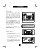
Headset Feature The SpectrumPLUSTM is equipped with a separate port for plugging in an optional headset. The port is located on the bottom of the base unit. The TeleMatrix FreeSpeechTM Talk Feature is a unique TeleMatrix feature that allows the user the freedom to “toggle” between the headset, handset and speakerphone modes during a conversation. LOW VOLT MW ON When the “HEADSET ON/OFF” key is ON, pressing the “SPEAKER” key will activate the speaker and disconnect the headset line automatically.
Using A Headset The “HEADSET ON/OFF” key controls the activation of the Headset. When using the headset feature, the handset remains on-hook at all times. Placing/Answering a Call using the Headset On/Off Feature ? ? ? ? ? To answer an incoming call, press the “HEADSET ON/OFF” key to activate the headset. The LED above the “HEADSET ON/OFF” key will be illuminated when in ON position. Adjust the volume, if necessary. Use the features of the headset that are available with the handset in use.
This page is intentionally left blank
Congratulations on the purchase of your TeleMatrix model SP-550 telephone. The SP-550 includes advanced features that are suitable in today’s business environment. TeleMatrix has designed the SP-550 to be simple to install and easy to use. The SP-550 is ideal for use behind Centrex or in a PBX environment. The SP-550 telephone is a precision electronic device that requires minimum maintenance.
IMPORTANT SAFETY INSTRUCTIONS When using your telephone equipment, basic safety precautions should always be followed to reduce the risk of fire, electric shock and injury to persons, including the following: 1. Read and understand all instructions. 2. Follow all warnings and instructions marked on the product. 3. Unplug this product from the wall outlet before cleaning. Do not use liquid cleaners or aerosol cleaners. Use a damp cloth for cleaning. 4.
FCC Part 15 Compliance Warning Changes or modifications to this unit not expressly approved by the party responsible for compliance could void the user's authority to operate the equipment. NOTE: This equipment has been tested and found to comply with the limits for Class B digital device, pursuant to Part 15 of the FCC Rules. These limits are designed to provide reasonable protection against harmful interference in a residential installation.
DOC - NOTICE AND LOAD NUMBER STATEMENT NOTICE: The Canadian Department of Communications label identifies certified equipment. This certification means that the equipment meets certain telecommunications network protective, operational and safety requirements. The Department does not guarantee the equipment will operate to the user's satisfaction. ''This product meets the applicable Industry Canada technical specifications.
Consumer Information: This equipment complies with Part 68 of the FCC rules and the requirements adopted by the ACTA. On the bottom of this equipment is a label that contains, among other information, a product identifier in the format US:2N3MT26B19550 If requested, this number must be provided to the telephone company. An applicable certification jacks Universal Service Order Codes (USOC) for the equipment is provided (i.e., RJ11C) in the packaging with each piece of approved terminal equipment.
Features .........................................………..................................... 9 Controls …….................................................................................. 10 Part List ………………………………………………………….. 14 Installation ....……......................................................................... 15 Wall Mounting .....…..............................……................................ 19 Switch Settings .....….......................….….......................................
• • • • • • One Line Operation SteelTrapTM Memory Technology (No Batteries Required) FreeSpeechTM Talk Feature: Allows Free Toggle between Handset, Headset and Speakerphone. Administrator Programming (Fixed): Dialing Access Number, Local Area Code Recognition, Live Keypad Dialing Option, Restrict 1+ Toll Restriction, 2.0S to 5.
TOP PANEL (18) (16) (19) (15) (14) (17) (2) (3) (4) (5) (13) (6) (7) Contrast Volume (9) 10 (12) (1) (10) (11) (8)
1. Speed Dial Feature Keys……………..……… 11 programmable one-touch keys used for speed dialing. 2. Disconnect Key ……………………...……… Used to disconnect the line, place new call or exit the store programming. 3. Store Key……………………………….….… Used to program features and speed dialing keys. 4. Pause Key ...............................………...….… Used to program a delay in speed dialing. 5. Redial Key ......................………………….... Redials the last number manually dialed. 6. Flash Key ..................
BOTTOM PANEL 12
1. Data Port .....................................…...………... Convenient port to connect to a computer, modem, fax or answering device. 2. Line Jack ……………………………………... Modular receptacle for connecting the line cord. 3. Headset Jack .................................…………… Convenient port for a headset connection. 4. Handset Jack ..................................………….. Connection for handset coil cord. 5. Power Adapter Receptacle ……..…………… For optional coaxial power adapter. 6.
Parts Check List The following parts are included with the SpectrumPLUSTM SP550: Base Unit Handset Two (2) 15 foot Modular telephone line cords. 10 foot Modular coiled handset cord. 6 inch Modular wall mount line cord. Power Adapter. Twenty-two (22) Speed Dial Preprinted Keycaps Four (4) Additional Clear Keycaps Two (2) Index Sheets 1. Clear plastic overlay 2. being remove from the index card area on the telephone. Tear index paper 3. Lift off clear plastic from the index sheet.
120V AC Outlet Recovery Power Adapter (provided) The 120 VOLT AC OUTLET RECOVERY POWER ADAPTER is an featured TeleMatrix product. It provides both the telephone lines and the power source in one cable (6P6C line cord) and is designed to recover the use of the power outlet. Connector Configuration The 120V Outlet Recovery Power Adapter has two (2) modular jacks. One jack is labeled “LINE” and the other jack is labeled “PHONE”. These jacks allow for a fully modular installation.
Installing The Wall Power Adapter (optional) To install, simply plug the power adapter into a standard 120V AC power outlet. A mounting hole is provided to secure the power pack to the AC wall outlet. Plug the AC power pack directly into the wall outlet and then plug the coaxial connector into the receptacle marked “POWER” located on the back of the telephone.
Connecting the Handset Cord A 10 foot modular coil handset cord is provided. (Be sure that the wall/desk elevation stand has not been attached). To install the cord, simply plug the short end of the handset cord into the modular jack on the handset. The long end of the handset cord plugs into the jack labeled “Handset” located on the bottom of the SpectrumPLUSTM base unit. Place the line cord into the line cord channel located directly below the jack.
Wall Mounting the SpectrumPLUS TM Telephone The SpectrumPLUSTM was designed to be conveniently wall mounted without requiring additional hardware. Retaining Clip 1. 2. 3. PULL OUTWARD UNSNAP ROTATE 180 . SNAP INTO PLACE. CLIP IS SPRING LOADED Follow these easy steps: 1.The handset retaining clip must be in the correct position to secure the handset into the handset cradle.
Message Waiting Light Indicator MW Light Indicator The SpectrumPLUSTM telephone has a Message Waiting (MW) Light Indicator (figure 1). The indicator will blink to indicate that a new message is in the user’s voice mailbox. The SpectrumPLUSTM supports the following telephone or PBX supplied message waiting signals: 1. Telephone Company VMWI Service (FSK signal compatible, subscription to local telephone company is required).* 2. Audible Stutter Dial Tone (SDT) signals provided by local telephone company.
Low Voltage LED Switch A low voltage LED switch is located on the bottom of the phone. The switch options are ON or OFF. The factory default is OFF. LOW VOLT MW ON OFF . System Hold Feature Option Switch (Administrator Feature) LOW VOLT MW ON OFF A hold feature switch is located on the bottom of the phone. The switch options are standard “LINE” hold or programmable* “SYSTEM” hold. The standard line hold allows for normal hold function operation.
Programming Set Up Of the SpectrumPLUS TM Telephone The SpectrumPLUSTM requires simple initial programming to set up the telephone. The program is designed for one Administrator and one or more users. Administrator programming features separate critical operating set up information from the user telephone functions. The Administrator Quick Program Guide for the SpectrumPLUS TM Telephone The SpectrumPLUSTM Quick Programming Guide is a summary list of set up options.
Programming Set Up of the SpectrumPLUS TM Telephone The SpectrumPLUSTM requires simple initial programming to set up the telephone. The program is designed for one Administrator and one or more users. Administrator programming features separate critical operating set up information from the user telephone functions. The Users Quick Program Guide for the SpectrumPLUS TM Telephone The SpectrumPLUSTM Quick Programming Guide is a summary list of set up options.
Set up using keypad dialing with automatic speaker activation or using key pad dialing and pressing dial key to act ivate. Live Dialpad Feature LIVE DIALPAD XXX (Administrator Programmable Only) This feature allows the Administrator to set up the telephone keypad ON HOOK dia ling method. PRESS 1=ON 2= OFF When LIVE DIALPAD is OFF, and the handset is ON HOOK, the user enters a number on the keypad must then press the “DIAL” key to activate dial tone.
Long distance restriction. Restrict any outgoing number dialing that begins with a “1” . RESTRICT 1+ Restrict 1+ Feature (Administrator Programmable Only) PRESS 1=ON 2= OFF This feature allows the Administrator to restrict the use of 1+ long distance calling. To enable RESTRICT 1+. 1. Press and hold the “STORE” key for 6 seconds. 12/01 PM 12:00 2. Press “STORE” multiple times until the LCD displays “RESTRICT 1+”. RESTRICT: 1+ 3. The display will read “ PRESS 1 = YES 2 = NO” 4.
Programming Flash Timing into Memory (Administrator Programmable Only) Flash Timing can be programmed into the SpectrumPLUSTM speed dial memory. This function allows the user to include a timed line break in the sequence of the dialing patterns when using the speed dial keys. This function may be required for accessing line features provided by your telephone system or local telephone company. The flash timing options are 100 through 1000 milliseconds, programmable in 100mS increments.
Programming Flash Timing (Administrator Programmable Only) Flash timing can be programmed for different timing options listed below. 1. Press and hold the “STORE” key for 6 seconds to enter set up. 2. Press the “STORE” key multiple times until the LCD display reads “FLASH TIME SET”. 3. Enter the flash timing to be stored into memory using the keypad by pressing the following keys on the keypad in the order shown. The keypad entry will be displayed on the LCD Screen.
Programming Pause Timing (Administrator Programmable Only) A Pause time between 2.0S to 5.0S can be programmed into memory at the option of the Administrator. This function allows the Administrator to provide delay timing for systems requiring different delay times and the user to delay the dialing pattern of a number. This function may be required for accessing line features provided by telephone provider or local telephone company.
Programming a Pause into Speed Dial Memory (Administrator Programmable Only) Pause(s) can be programmed into the speed dial memory at the option of the Administrator. This function puts a delay the dialing pattern of a number. Multiple pauses can be programmed into speed dial for added pause time. To Program A Timed Pause 1. To store a Pause into Speed Dial memory, simply press the “PAUSE” key in the numbering sequence when programming speed dial memory keys. 2. See page 34 for programming speed dial.
Programming the Access Number into Memory (Administrator Programmable Only) In some cases, a digit or digits are required to access an outside line (i.e. 9) . The Access Number can be programmed into the phone memory at the option of the Administrator. This function allows the user to automatically dial number(s) that are required prior to dialing the displayed number. ? ? The number to be programmed is based on your specific area dialing requirements and may not be required.
Programming the Area Code into Memory (Administrator Programmable Only) An Area Code can be programmed into the phone memory at the option of the Administrator. The Area Code is programmed into memory to allow the phone to recognize the local area code. When this number is programmed, the Area Code WILL NOT be dialed when calling back a number within the same local calling area. Set up local area code to recognize local incoming calls.
Programming Voice Mail (Administrator Programmable Only) Voice Mail (VM) access numbers and their associated “Personal Identification Number” (PIN) can be programmed into phone memory when Voice Mail is activated. The feature allows the user to automatically obtain their voice mail using the SpectrumPLUSTM TouchLite R speed dial key. VOICE MAIL NO. PIN NUMBER SECOND OF WAIT? Add the Voice Mail number to dial. Add users PIN.
Programming Voice Mail (Administrator Programmable Only) To program the SpectrumPLUSTM one touch “MESSAGE WAITING” speed dial key, follow these programming instructions. Programming Voice Mail Dialing 1. Press and hold the “STORE” key to activate Administrator mode. 2. Press the “STORE” key multiple times until “VOICE MAIL NO.” is displayed on the LCD screen. 3. Enter the voice mail number. The area code is not required if AREA CODE is programmed into memory. 4.
Programming Procedure for SpectrumPlus tm Speed Dial Features (Administrator Programmable Only) (Manual Entry of Characters) The SpectrumPLUSTM Telephone has 11 one-touch speed dial locations that are convenient for dialing frequently used telephone numbers. This feature is under Administrative control so user changes do not occur. ? ? ? Speed dial programming must be done with the telephone plugged into the telephone line and power adapter. Programming can be performed with the telephone on-hook only.
To Verify Speed Dial Programming (Administrator Programmable Only) The contents of each speed dial location can be verified or “checked” while the SpectrumPLUSTM unit is in the programming mode. ? Memory verification is accomplished with the SpectrumPlus tm on-hook. To Verify Speed Dial Locations 1. Press and hold the “STORE” key for 6 seconds to activate Administrator mode. The words “ENTER ACCESS NO.” will appear (figure 1). 2. Next, press the speed dial location key to verify.
Manual Entry From Keypad (Guide) Use the following chart to add characters when programming into memory. Press Keypad:: Once Twice Three Times Four Times No. 1 1 No. 2 A B C 2 No. 3 D E F 3 No. 4 G H I 4 No. 5 J K L 5 No. 6 M N O 6 No. 7 P Q R S No. 8 T U V 8 No. 9 W X Y Z 9 No. 0 0 No. * adds space = * No. # .
Headset Feature The SpectrumPLUSTM is equipped with a separate port for plugging in an optional headset. The port is located on the bottom of the base unit. The TeleMatrix FreeSpeechTM Talk Feature is a unique TeleMatrix feature that allows the user the freedom to “toggle” between the headset, handset and speakerphone modes during a conversation. LOW VOLT MW ON OFF When the “HEADSET ON/OFF” key is ON, pressing the “SPEAKER” key will activate the speaker and disconnect the headset line automatically.
Using A Headset The “HEADSET ON/OFF” key controls the activation of the Headset. When using the headset feature, the handset remains on-hook at all times. Placing/Answering a Call using the Headset On/Off Feature • • • • • To answer an incoming call, press the “HEADSET ON/OFF” key to activate the headset. The LED above the “HEADSET ON/OFF” key will be illuminated when in ON position. Adjust the volume, if necessary. Use the features of the headset that are available with the handset in use.
Caller Identification (Caller ID*) LCD Display Type II Caller ID Technology The SpectrumPLUSTM LCD display supports Type II Caller ID*. This type of Caller ID displays the identity of a second incoming call while the user is actively on a first incoming call. The user has the option to answer the call or allow the call to automatically be forwarded to voice mail*.
Caller Identification (Caller ID) LCD Display Adjustments LCD Tilt Angle Feature The LCD can be tilted upward for direct viewing and easy reading. Tilt the LCD to the desired position by lifting up the back of LCD housing. (60° maximum upward tilt). LCD Contrast Feature (4-step) The LCD characters can be lightened or darkened using the volume control key. 12/01 While the handset is in the ON HOOK position, simply press the volume control key to adjust the contrast of the LCD screen.
NEW RPT CALLS 12/01 PM12:00 03 MO1 LCD (Caller ID* Display) Featured Icons CW Caller Number Caller Name PhBook NEW RPT CALLS Indicates New Call or Repeat Call Indicates Speaker is ON* 03:68 Delete Dial 12/01 Shows current date or date of call record in memory 12:00 Shows current time or time of call record in memory PM Indicates Message is Waiting in Voice Mail CW 03 M01 Indicates Handset is In-Use Indicates Call Waiting Caller is On Line Shows Caller ID Record Location in Ca
NEW RPT CALLS 12/01 PM12:00 03 LCD (Caller ID* Display) Information Management Keys CW Caller Number MO1 Caller Name PhBook Delete Dial DOWN Key Used to Scroll LCD Records Downward UP Key Used to Scroll LCD Records Upward PhBook Used to Enter Phonebook Delete Used to Delete Caller Log Record or Phonebook Record Dial 1 2 3 4 5 6 7 8 9 * 0 # Store Used to Dial Record Displayed Number on the LCD Screen Used to Enter the LCD’s Edit Mode and to Edit or Enter LCD Information U
LCD (Caller ID* Display) Information when On Hook (Without Messages) 12/01 PM12:26 -00- -00- NEW TOTAL PhBook Delete Dial 12/01 Shows current date 12:26 Shows current time PM -00- Indicates Zero New Messages -00- Indicates Zero Total Messages NEW Indicates Number of New Incoming Calls Since Last Retrieved Messages TOTAL Indicates Total of Messages Received and Stored into Memory (99 maximum) * Caller ID and Class Visual Message Waiting are features that require subscription to your local teleph
LCD (Caller ID Display) Information when On Hook (with Messages) 12/01 PM12:26 -02- -03- NEW TOTAL PhBook Delete Dial 12/01 Shows current date 12:26 Shows current time PM Indicates Message is Waiting in Voice Mail -02- Indicates Two New Messages -03- Indicates Three Total Messages NEW Indicates Number of New Incoming Calls Since Last Retrieved Messages TOTAL Indicates Total of Messages Received and Stored into Memory (99 maximun) * Caller ID and Class Visual Message Waiting are features th
LCD (Caller ID* Display) Information when Dialing 12/01 Lift Handset PM12:00 IN - USE PhBook Delete Dial After Dialing, Elapsed Timer Activates on First Ring PM12:00 12/01 7196388821 IN USE 0:22 PhBook Delete Dial * Caller ID and Class Visual Message Waiting are features that require subscription to your local telephone company provided services. These telephone features will not work unless you are a subscriber.
LCD (Caller ID* Display) Information when Receiving Incoming Call Telephone Ringing (with CID Message Waiting activated) NEW CALL 12/01 PM12:00 PERSONS NUMBER PERSONS NAME If caller called RPT earlier and is on CALL the caller log record, REPEAT CALL will appear. PhBook Delete Dial 12/01 PM12:00 After Answering Call (with CID Message Waiting activated) A person’s name and number will NOT appear if you are not subscribed to a Caller ID and Class Visual Message Waiting System.
Type II Caller Identification (Caller ID) Display Type The SpectrumPLUSTM LCD display supports Type II Caller ID*. This type of Caller ID displays the identity of a second incoming call while the user is actively on a first incoming call. The user has the option to answer the call or allow the call to be forwarded automatically to the Users Voice Mail*. ! NOTE: When the CW call goes to voice mail, the information can be retrieved at a later time using the call log.
Caller Identification (Caller ID*) Date and Time Information* Setting Date & Time Manually Setting Date & Time Automatically The SpectrumPLUStm Date & Time functions are user/installer programmable. The Date & Time can be set up by the user. See User Programming for further instructions. Once the programming is complete, the Date & Time are maintained internally by the SpectrumPLUStm. The SpectrumPLUStm Date & Time functions are system programmable when Caller ID service is activated.
Caller Identification (Caller ID*) Storage Capacity Caller ID Storage Capacity Phone Book Storage Capacity The SpectrumPLUStm Caller ID will store 100 records (numbers and names). When memory is full, the oldest of the 100th call records will automatically be deleted when the newest call is accepted into memory. The phonebook storage capacity holds 100 records (numbers and names). When memory is full, records will not delete automatically.
Scrolling and Call Back Feature The “DIAL” key allows the user to call back either stored records or the displayed number on the LCD. A displayed number on the LCD comes from incoming calls, or from the Phonebook memory. The Dial Back editing feature allows the user to add or delete characters to accurately pattern the number to be called. To activate the editing feature, press any character on the keypad to activate after the record is found.
Deleting a Call Log Record Delete Individual Stored Call Record 1. Press the “↑” or “↓” key to activate stored memory. The LCD screen will display a record. Use the “↑” or “↓” key to scroll to the caller record that is to be deleted. 12/01 03 PM 7196388821 DELETE? 2. Press the “DELETE” key once and the LCD will display the question DELETE?. 3. Press the “DELETE” key a second time to delete. 12:00 PhBook Delete or Dial Press quickly Delete All Stored Call Records 1. 2.
Adding a Phonebook Record From a Caller ID Record The Phonebook can automatically save a caller ID record into the Phonebook memory. To add the record, simply find the record using the LCD management keys and press the “PhBook” key. Adding a Caller Record To The Phonebook 1. Press the “↑” or “↓” key to activate stored memory. The LCD screen will display a record. Scroll to the caller record to be placed in the Phonebook (figure 1). 2.
Adding A Phonebook Record Manually Phonebook records may be added manually. To add a record, simply follow the instructions below. All stored records in the Phonebook will be displayed in alphabetic order. Manually Adding A Phonebook Record Into Memory 12/01 1. The phone must be ON-HOOK (in cradle). PM12:00 ENTER NUMBER 2. Press the “STORE” key. 3. Press the “PhBook” key. The display will show “ENTER NUMBER” (figure 1). Delete PhBook Dial Figure 1 4. Input the number using the keypad (figure 2).
Dialing From the Phonebook Directory To Dial From the Phonebook Directory 1. Press the “PhBook” key to enter into the Phonebook mode. 2. To locate the desired record, Scroll the “↑” or “↓” key or use the Hyperlink Feature below along with the “↑” or “↓” key to find a record. (See the Hyperlink Feature note below). 3. Once the record is found, press the “DIAL” key.
Call Record Editing Prior to Dialing To Add Characters to the Displayed Number To Delete Characters from the Displayed Number 1. Press the “↑” or “↓” key to activate the display for scrolling. 2. Scroll the “↑” or “↓” key to find the number to be dialed. 3. Activate the editing feature by pressing any number on the keypad. (Note that the key pressed will be displayed on the LCD). 4. Press the keypad number you require and it will appear on the LCD prior to the number on the display 5.
Other LCD Displays This message will display when there are no call records received since last using the Caller ID features menu when the “↑” or “↓” key is pressed. 12/01 PM 12:00 “No Calls” Display NO CALLS Indicates that there was a line error when attempting to connect to the dialed party. Retry the phone call. If “line error” continues, check for dial tone. If no dial tone, call your local service provider.
Speaker Line Indicators Contrast When the “SPEAKER” key is activated, the in-use light illuminates steadily RED above the “SPEAKER” key. The LCD will display “SPEAKER” when active Hold Key Indicators Volume Contrast Volume When the “HOLD” key is activated, the light above the HOLD KEY will be steadily RED. The LCD will display “HOLD” when active Headset Key Indicators Contrast Volume When the “HEADSET ON/OFF” key is activated, the Headset indicator will be steadily RED.
Placing a Call Using the Speakerphone The SpectrumPLUSTM is equipped with a high quality speakerphone feature to allow for hands-free operation. To use, simply press the “SPEAKER” key when placing or answering a call. The telephone line will activate automatically. When the “DIALPAD” Feature is programmed to be ON, the speakerphone will active automatically when pressing and number on the dial pad keys. The LED above the “SPEAKER” key will illuminate to indicate that the speakerphone is in-use.
Using the Data Port The SpectrumPLUSTM is equipped with a convenient data port on the bottom of the base unit. This modular receptacle is used to plug in any standard telephone device such as a computer modem, answering machine , or fax machine.
Using the Hold Feature The “HOLD” key is used to place a caller on hold. To use, simply press the “HOLD” key. The LED above the HOLD key will illuminate to indicate that the line is on hold. The LCD will display the word “HOLD” when active. Contrast Volume When the “HOLD” key is active, the handset can be lifted off-hook or returned to its on-hook position and the line will not be disconnected.
Using The Mute Feature A “MUTE” key is provided to allow pr ivacy during a background conversation. When the “MUTE” key is activated, the microphones in the handset, speakerphone and/or headset are disabled. When the “MUTE” key is activated, the caller will not hear voice. “Mute” will be displayed on the LCD to show that the feature is activate. To de-activate, press the “MUTE” key again.
Using the Redial Feature The “REDIAL” key is used to automatically redial the last number that was dialed from the keypad. To use: ? ? ? Lift the handset (or activate the speaker). Press the “REDIAL” key. The last number dialed will be redialed. OR ? ? Press the “REDIAL” key. The last number dialed will be redialed. (automatically activate the speaker).
Using The Disconnect Feature Key The “DISC” (DISCONNECT) key is a 2 second electronic timed line break. The key can be used to automatically hang-up the call that you are currently on and regain a new dial tone to establish a new call. To use: ? ? ? ? Simply press the “DISC” key when the conversation is complete. The “DISC” key can be used in Speaker mode. The “DISC” key can be used with headset or handset activation.
Handset Volume Control The SpectrumPLUSTM is equipped with an ADA/FCC compliant handset volume control located on the front of the phone. When the right end of the “VOLUME” key is pressed, the volume of the handset receiver is increased. Contrast Volume When the left end of the “VOLUME” key is pressed, the volume of the handset receiver is decreased. The “VOLUME” key is an eight-step volume control.
Keep the telephone dry. If it gets wet on the outside, wipe it dry immediately. Liquids might contain minerals that can corrode the electronic circuits. Do not touch the unit if submerged in water. Call for assistance. Use and store the telephone only in normal temperature environments. Temperature extremes can shorten the life of electronic devices, damage batteries, and distort or melt plastic parts. Avoid direct sunlight.
When problems arise during installation or service that cannot be resolved using this or related documents, contact the TeleMatrix Priority Care Department, Monday through Friday, 8:30a.m. - 4:30p.m. MST: Toll Free: 1-800-462-9446 Direct: 719-638-8821 Fax: 719-638-8815 www.telematrixusa.com Many times a problem is either installation or user related. Please contact TeleMatrix PRIOR to sending a telephone to our service center for repair. In the unlikely event that a factory repair is necessary: 1.
Parts List The following SpectrumPLUStm accessories and parts are available from TeleMatrix.
STATEMENT OF LIMITED WARRANTY TeleMatrix, Inc.