
Owner's manual


• If the field wiring must cross ac or power cables, ensure that they
cross at right angles.
• To limit the pickup of electrical noise, keep signal wires as far from
power and load lines as possible.
• Ground the shield drain wire at only one end of the cable. The
preferred location is at the shield connections at the ControlLogix
chassis. (Refer to IEEE Std. 518, Section 6.4.2.7 or contact your sensor
manufacturer for additional details.)
• Tighten screw terminals with care. Excessive tightening can strip a
screw.
• Follow system grounding and wiring guidelines found in your
ControlLogix Installation and Operation Manual.
Preparing and Wiring the Cables
To prepare and connect cable leads and drain wires, follow these steps:
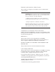
Signal Wires
Drain Wire
Signal Wires
Cable
(Remove foil shield and drain wire
from sensor-end of the cable.)
(At the module-end of the cable, extract
the drain wire but remove the foil shield.)
1. At each end of the cable, strip some casing to expose individual
wires.
2. Trim signal wires to 5-inch lengths beyond the cable casing. Strip
about 3/16 inch (4.76 mm) of insulation to expose the ends of the wires.
3. At the module-end of the cables (see figure above):
- extract the drain wire and signal wires
- remove the foil shield
- bundle the input cables with a cable strap
4. Connect pairs of drain wires together, Channels 0 and 1, Channels 2
and 3, Channels 4 and 5, Channels 6 and 7. Keep drain wires as short as
possible.
5. Connect the drain wires to the grounding lug on the PLC chassis.
6. Connect the signal wires of each channel to the terminal block.
Important: Only after verifying that your connections are correct for
each channel, trim the lengths to keep them short. Avoid cutting leads
too short.
7. At the source-end of cables from devices:
- remove the drain wire and foil shield
- apply shrink wrap as an option
- connect to mV devices keeping the leads short