
Owner's manual


30 ControlLogix
™
Counter Module
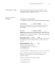
Uni-Directional
With this configuration, the input increments in an upward direction. All 8
channels may be configured in the unidirectional mode. Every clock pulse
will increment the counter on the rising edge. Note: The direction of the
counter may be inverted by setting the Count Direction bit described in the
Configuration chapter.
Bi-Directional
The bidirectional counter requires 2 input channels. In this mode one
channel is used as the counter input and the 2
nd
channel is used to
determine the count direction. The counter will increment when the
Direction Channel value is 0, and will decrement when the Counter
Direction Channel value is 1.
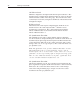
X1 Quadrature Encoder
The quadrature mode requires 2 input channels. When a quadrature
encoder is attached to an input channel pair, A and B, the count direction is
determined by the phase angle between inputs A and B. If A leads B, the
counter increments. If B leads A, the counter decrements. (The counter
changes value only on one edge of input 1.) The counter increments once
per quadrature cycle.
Note: The Quadrature mode provides additional Anti-Jitter circuitry.
This distinguishes between a valid quadrature sequence and an
invalid sequence due to electrical noise or jitter. Jitter can occur if a
quadrature encoder stops rotating right at an input sensor trip point.
This can cause additional unwanted clock pulses. Quadrature mode
can detect invalid transitions and filter these out.
X4 Quadrature Encoder
Like the X1 quadrature encoder, the count direction is determined by the
phase angle between inputs A and B. If A leads B, the counter increments.
If B leads A, the counter decrements. However, the counter changes
value on the rising and falling edges of inputs A and B. The counter
increments four times per quadrature cycle.