
User Manual


Chapter 3: Installation and Wiring
User’s Manual 03 00217-03 Rev. A
3-7
2. Using the assemb led modules as a template, carefully mark the center of all module-
mounting holes on the panel.
3. Return the assembled modules to the clean work surface, including any previously
mounted modules.
4. Drill and tap the mounting holes for the recommended M4 or #8 screw.
5. Place the modules back on the panel, and check for proper hole alignment.
6. Attach the modules to the panel using the mounting screws.
NOTE If mounting more modules, mount only the last one of this group and put the
others aside. This reduces remounting time during drilling and tapping of the next
group.
7. Repeat steps 1 to 6 for any remaining modules.
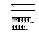
3.5.3 DIN Rail Mounting
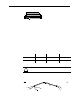
The module can be mounted using the following DIN rails:
35 x 7.5 mm (EN 50 022 - 35 x 7.5), or
35 x 15 mm (EN 50 022 - 35 x 15).
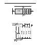
Before mounting the module on a DIN rail, close the DIN rail latches. Press the DIN rail
mounting area of the module against the DIN rail. The latches will momentarily open and
lock into place.
Section 3.6
Replacing a Single
Module within
a System
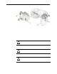
The module can be replaced while the system is mounted to a panel (or DIN rail). Follow
these steps in order:
1. Remove power. See important note at the beginning of this chapter.
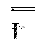
2. On the module to be removed, remove the upper and lower mounting screws from
the module (or open the DIN latches using a flat-blade or phillips-style screwdriver).
3. Move the bus lever to the right to disconnect (unlock) the bus.
4. On the right-side adjacent module, move its bus lever to the right (unlock) to
disconnect it from the module to be removed.
5. Gently slide the disconnected module forward. If you feel excessive resistance,
check that the module has been disconnected from the bus, and that both mounting
screws have been removed (or DIN latches opened).
NOTE: It may be necessary to rock the module slightly from front to back to remove it,
or, in a panel-mounted system, to loosen the screws of adjacent modules.
6. Before installing the replacement module, be sure that the bus lever on the module to
be installed and on the right-side adjacent module or end cap are in the unlocked
(fully right) position.
7. Slide the replacement module into the open slot.
8. Connect the modules tog e ther by locking (fully left) the bus levers on the
replacement module and the right-side adjacent module.
9. Replace the mounting screws (or snap the module onto the DIN rail).
Section 3.7
Field Wiring
Connections &
System Wiring
Guidelines
Consider the following when wiring your system: