
User Manual


Chapter 1: Module Overview
U ser 's M a n u a l 0 300 21 5- 03 R ev. A
1-3
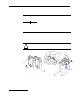
5a movable bus connector (bus interface) with female pins
5b stationary bus connector (bus interface) with male pins
6 nameplate label
7a uppe r to ngue-and-groove slots
7b lower tongue-and-groove slots
8a upper DIN r a il latch
8b lower DIN rail latch
9 write-on label for user identi fi cation tags
10 removable terminal block (RTB) with finger-safe cover
10a RTB upper retaini ng screw
10b RTB lower retaining screw
1.4.1 General Diagnostic Features
The module contains a diagnostic LED that helps you identify the source of problems that
may occur during power-up or during normal channel operation. The LED indicates both
status and power. Power-up and channel diagnostics are explained in Chapter 9
Diagnostics and Troubleshooting.
Sec t ion 1.5
System
Overview
The modules communicate to the controller through the bus interface. The modules also
receive 5 and 2 4V dc po wer through the bus inter face.
1.5.1 System Operation
At power-up, the module performs a check of its internal circuits, memory, and basic
functions. During this time, the module status LED remains off. If no faults are found
during power-up diagnostics, the module status LED is turned on.
After power-up checks are complete, the module waits for valid channel con fi guration
data. If an invalid configuration is detected , the mod ule generates a configuration error .
Once a channel is properly configured and enabled, it continuously converts the input
data to a value within the range selected for that channel.
Each time a channel is read by the input module, that data value is tested by the module
for an over-range, under-range, open-circuit, or “input data not valid” condition. If such a
condition is detected, a unique bit is set in the channel statu s word. The channel status
word is described in Section 6.3 Input Data File.
Using the module image table, the controller reads the two’s complement binary
converted input data from the module. This typically occurs at the end of the program
scan or when commanded by the control program. If the controller and the module
determine that the data transfer has been made without error, the data is used in the
control program.