Installation Instructions for Dryers Original Instructions Keep These Instructions for Future Reference. CAUTION: Read the instructions before using the machine. (If this machine changes ownership, this manual must accompany machine.) www.alliancelaundry.com Part No.
WARNING WARNING • Risk of fire. Highly flammable material. • W881 IMPORTANT: The electrical installation in the site shall comply with the Australian Electrical Standards, AS3000, SAA wiring rules, and such local regulations that might apply. In Australia and New Zealand, installation must comply with the Gas Installations Standard AS/NZS 5601 Part 1: General Installations. The maximum drying load (dry weight) shall not exceed 9 kg [20 pounds]. • Read all instructions before using unit.
WARNING To reduce the risk of severe injury or death, follow all installation instructions. Save these instructions. W894 WARNING FOR YOUR SAFETY Do not store or use gasoline or other flammable vapors and liquids in the vicinity of this or any other appliance. W053 This product uses FreeRTOS V7.2.0 (www.freertos.org).
Table of Contents Dimensions............................................................................................. 6 Installation............................................................................................. 8 Before You Start............................................................................................. 8 Supplies..................................................................................................... 8 Order of Installation Steps.............................
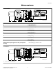
Dimensions Dimensions Electric Models A B G I K J C E H D F A * 1027 mm [40.42 in.] B * 1006 mm [39.61 in.] C * 392 mm [15.44 in.] D * 102 mm [4 in.] E 391 mm [15.4 in.] F 683 mm [26.875 in.] G * 114 mm [4.5 in.] H 10 mm [0.4 in.] I 203 mm [8 in.] J 711 mm [28 in.] K 597 mm [23.5 in.] NOTE: Exhaust openings are 102 mm [4 inch] metal ducting. DRY2638N_SVG * With leveling legs turned into base.
Dimensions A *1027 mm [40.42 in.] B *1006 mm [39.61 in.] C *392 mm [15.44 in.] D *70 mm [2.8 in.] E 60 mm [2.3 in.] F 391 mm [15.4 in.] G 683 mm [26.875 in.] H 102 mm [4 in.] I *114 mm [4.5 in.] J 10 mm [0.4 in.] K 203 mm [8 in.] L 711 mm [28 in.] M 597 mm [23.5 in.] NOTE: Exhaust openings are 102 mm [4 inch] metal ducting. * With leveling legs turned into base. NOTE: Gas models cannot be vented out left side of cabinet because of burner housing.
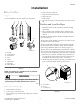
Installation Installation Before You Start 4. 5. 6. 7. 8. Supplies For most installations, the basic supplies you will need are: 1 2 3 4 Reverse the door, if desired. Wipe out the inside of the dryer. Plug in the dryer. Recheck steps. Start and run the dryer in a heat setting to verify dryer is heating. Position and Level the Dryer 1. Install dryer before washer. This allows room for attaching exhaust duct. 2. Select a location with a solid floor.
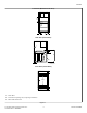
Installation Front View (Without Closet Door) B A A DRY2640N_SVG Side View (Closet Door) 1 E D A H 3 C DRY2641N_SVG Front View (Closet Door) F 2 (G) F DRY2637N_SVG 1. Closet Door 2. Centered Air Openings (G) (2 Openings minimum) 3. Outer Wall of Enclosure Figure 3 © Copyright, Alliance Laundry Systems LLC - DO NOT COPY or TRANSMIT 9 Part No.
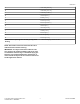
Installation Area Free Standing/Alcove Installation Description Closet Installation A* Dryer sides and rear clearance 0 mm [0 in.] 0 mm [0 in.] B Dryer top clearance 305 mm [12 in.] 305 mm [12 in.] C Dryer front clearance Not Applicable 51 mm [2 in.] D Exhaust duct clearance to com- 51 mm [2 in.] bustible material 51 mm [2 in.] E Weather hood to ground clearance 305 mm [12 in.] 305 mm [12 in.] F Distance from floor or ceiling to air opening edge Not Applicable 76 mm [3 in.
Installation • WARNING To reduce the risk of fire, the exhaust duct and weather hood MUST be fabricated of a material that will not support combustion. Rigid or flexible metal pipe is recommended for a clothes dryer. W048 • • • • • WARNING To reduce the risk of fire due to increased static pressure, we do not recommend installation of inline secondary lint filters or lint collectors. If secondary systems are mandated, frequently clean the system to assure safe operation.
Installation IMPORTANT: DO NOT block the airflow at the bottom of the dryer’s front panel with laundry, rugs, etc. Blockage will decrease airflow through the dryer, thus reducing the efficiency of the dryer. To prevent backdraft when dryer is not in operation, outer end of exhaust pipe must have a weather hood with hinged dampers (obtain locally). NOTE: Weather hood should be installed at least 305 mm [12 inches] above the ground.
Installation NOTE: L.P. gas, 93.1 MJ/m3 [2500 Btu/ft3], service must be supplied at 2.75 kPa [11.04 inch] water column pressure and a vent to the outdoors must be provided. 4. If local codes allow the use of flexible gas tubing, connect the 9.5 mm [3/8 inch] NPT (National Pipe Thread) gas connection at the rear of the dryer to the laundry room’s gas line with new flexible stainless steel tubing (using design certified Australian Gas Association connector only).
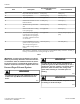
Installation Natural Gas Altitude Adjustments Altitude Orifice Size m [ft] mm [inches] No. Part Number 760 [2500] 45 2.08 [0.0820] D503779 1370 [4500] 46 2.06 [0.0810] D503780 1830 [6000] 47 1.99 [0.0785] D503781 2290 [7500] 48 1.93 [0.0760] D503782 2900 [9500] 49 1.85 [0.0730] D503783 3355 [11000] 50 1.78 [0.0700] D503784 D272P_SVG Figure 7 3. Pull bottom of door liner out, then pull down, removing door liner from door panel. Table 3 L.P.
Installation 6. Insert liner under flange on bottom of door, then push top of door liner into place. B A D606I_SVG Figure 14 DRY1918N_SVG Figure 11 Wipe Out Inside of Dryer Before using dryer for the first time, use an all-purpose cleaner, or a detergent and water solution, and a damp cloth to remove shipping dust from inside dryer drum. 7. Reinstall nine screws removed in Step 2. DRY1919N_SVG Figure 12 8. Using screwdriver, remove two door plugs, and reinstall on opposite side of door opening.
Installation This dryer is designed to be operated on a two-wire, plus earth/ ground, 240 Volt, 50 Hertz, single-phase circuit, fused at 20 Amperes. WARNING To reduce the risk of fire, electric shock or personal injury, all wiring and earthing to the dryer MUST conform with the latest edition of the Australian Electrical Standards, AS3000, SAA wiring rules, and such local regulations that might apply.
Installation Recheck Steps Refer to Installer Checklist on the back cover of this manual and make sure that dryer is installed correctly. 1 Check Heat Source 2 Electric Dryers 1. Close the loading door and start the dryer in a heat setting (refer to the operation instructions). 2. After the dryer has operated for three minutes, the exhaust air or exhaust pipe should be warm. 3 Gas Dryers 10A IMPORTANT: This operation is to be conducted by qualified personnel only. 1.
Installation Shut-off Valve Only Applicable on Certain Models 5 1 6 4 3 2 DRY2753N_SVG 1. 2. 3. 4. 5. 6. Air Shutter Lockscrew Air Shutter 3.1 mm [1/8 in.] Pipe Plug (For checking manifold pressure) Shut-off Valve Open Position Shut-off Valve Closed Position Shut-off Valve Handle Figure 18 All Dryers If the dryer heat source is not functioning correctly, refer to the Troubleshooting section of the Dryer User’s Guide for corrective action.
Installer Checklist Installer Checklist Fast Track for Installing the Dryer 1 Position and Level the Dryer. 5 CHECK Wipe Out Inside of Dryer. CHECK DRY2504N_SVG1 DRY2634N_SVG 2 Connect Dryer Exhaust System. 6 CHECK Plug In the Dryer. CHECK TLW2170N_SVG DRY2501N_SVG1 3 GAS ONLY • Connect Gas Supply Pipe. • Check for Gas Leaks. 7 NOTE: Refer to User's Guide for proper operation. NOTE: Must be connected by a licensed professional. D233I_SVG1 CHECK 4 Recheck Steps.