Installation Instructions for Stacked Washer/Dryers Original Instructions Keep These Instructions for Future Reference. CAUTION: Read the instructions before using the machine. (If this machine changes ownership, this manual must accompany machine.) www.alliancelaundry.com Part No.
WARNING WARNING • Risk of fire. Highly flammable material. • W881 IMPORTANT: The electrical installation in the site shall comply with the Australian Electrical Standards, AS3000, SAA wiring rules, and such local regulations that might apply. In Australia and New Zealand, installation must comply with the Gas Installations Standard AS/NZS 5601 Part 1: General Installations. The maximum washing load (dry weight) shall not exceed 10 kg [22 pounds].
WARNING To reduce the risk of severe injury or death, follow all installation instructions. Save these instructions. W894 WARNING FOR YOUR SAFETY Do not store or use gasoline or other flammable vapors and liquids in the vicinity of this or any other appliance. W053 This product uses FreeRTOS V7.2.0 (www.freertos.org).
Table of Contents Dimensions............................................................................................. 6 Installation............................................................................................. 9 Before You Start............................................................................................. 9 Tools..........................................................................................................9 Order of Installation Steps............................
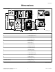
Dimensions Dimensions Electric Models C G F D A E L B H M J Q O P K N I SWD1003N_SVG A * 1678 mm [66.06 in.] B * 1447 mm [56.97 in.] C 597 mm [23.5 in.] D 213 mm [8.375 in.] E 610 mm [24 in.] F 203 mm [8 in.] G 391 mm [15.4 in.] H * 938 mm [36.9 in.] I * 371 mm [14.6 in.] J * 813 mm [32 in.] K 683 mm [26.875 in.] L * 1184 mm [46.62 in.] M * 1986 mm [78.17 in.] N 52 mm [2.04 in.] O 704 mm [27.73 in.] P (with door closed) 38 mm [1.5 in.] Q * 333 mm [13.1 in.
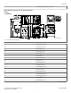
Dimensions * With leveling legs turned into base. NOTE: Exhaust openings are 102 mm [4 inch] metal ducting. Gas Models C G F 1 D E H O A B I N L K S Q R M P J SWD1004N_SVG 1. 3/8 in. NPT Gas Connection A *1678 mm [66.06 in.] B *1447 mm [56.97 in.] C 597 mm [23.5 in.] D 213 mm [8.375 in.] E 610 mm [24 in.] F 203 mm [8 in.] G 391 mm [15.4 in.] H 59 mm [2.3 in.] I *938 mm [36.9 in.] J *371 mm [14.6 in.] K *1140 mm [44.87 in.] L *813 mm [32 in.] M 683 mm [26.875 in.
Dimensions R (with door closed) 38 mm [1.5 in.] S *333 mm [13.1 in.] * With leveling legs turned into base. NOTE: Exhaust openings are 102 mm [4 inch] metal ducting. © Copyright, Alliance Laundry Systems LLC - DO NOT COPY or TRANSMIT 8 Part No.
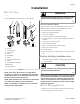
Installation Installation Before You Start WARNING Tools Any disassembly requiring the use of tools must be performed by a suitably qualified service person. For most installations, the basic tools you will need are: 1 2 3 4 W299 5 Order of Installation Steps The proper order of steps must be followed to ensure correct installation. Refer to the list below when installing your unit. 6 1. 2. 3. 4. 5. Position unit near area of installation. Remove the shipping materials. Connect the fill hoses.
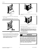
Installation FLW2297N_SVG1 Figure 4 FLW2378N_SVG Figure 2 6. Insert two plugs included in accessories bag into rear shipping bolt holes. 2. Remove two 9/16 inch bolts and washers holding shipping brace to weight. 3. Remove two 9/16 inch bolts and washers holding shipping brace to washer base and remove brace. FLW2358N_SVG Figure 5 7. Replace front access panel. 8. Save all shipping materials. They must be reinstalled any time washer is moved more than four feet.
Installation Water Supply Requirements Water supply taps must fit standard 19 mm [3/4 inch] female garden hose couplings. DO NOT USE SLIP-ON OR CLAMP-ON CONNECTIONS. NOTE: Water supply taps should be readily accessible to permit turning them off when washer is not being used. Recommended cold water temperature is 10° to 24° Celsius [50° to 75° Fahrenheit]. Recommended maximum hot water temperature is 51° Celsius [125° Fahrenheit]. Warm water is a mixture of hot and cold water.
Installation 6. Turn water on and check for leaks. 7. If leaks are found, retighten the hose couplings. 8. Continue tightening and rechecking until no leaks are found. 1 1 COLD HOT 5 9 2 3 4 8 7 2 6 W005I_SVG FLW2446N_SVG 1. Tap 2. Fill Hoses 3. Install this end of hose to valve connections at rear of washer 4. Plain Rubber Washer 5. Cold Water Connection 6. Hot Water Connection 7. Install this end of hose to water supply tap (Black colored or hex nut shaped coupling for BSPP thread) 8.
Installation a. Insert the end of the beaded strap into the larger hole found on the end of the strap. b. Tighten to desired fit. c. Lock strap in place by pulling beaded strap into the tampered smaller opening of the beaded strap end. A distinct snap noise should be heard once the strap is properly seated. d. Pull on the strap once locked in place to ensure beaded strap is properly installed. This will prevent the drain hose from dislodging from drain receptacle during use. 1 2 3 H023i_SVG 1.
Installation Gas Dryers - Connect Gas Supply Pipe WARNING NOTE: The gas service to a gas dryer must conform with the local codes and ordinances and in Australia and New Zealand, installation must comply with the Gas Installations Standard AS/ NZS 5601 Part 1: General Installations. In the absence of local codes and ordinances, applicable National codes should be followed. 1.
Installation 5. The gas line to your laundry room should be made of black iron pipe. A 9.5 mm [3/8 inch] pipe with an inside diameter of 11.7 mm [0.46 inch] will be adequate if length of supply line is not over 6 m [20 feet]. If length exceeds this, use 12.7 mm [1/2 inch] pipe. If copper semi-rigid tubing is used it must be internally tinned or equivalently treated to resist sulfur corrosion.
Installation • • • • • Static pressure in exhaust duct should not be greater than 10 mm water column [0.4 inches water column], measured with manometer placed on exhaust duct 610 mm [two feet] from dryer (check with dryer running and no load). Exhausting dryer in hard-to-reach locations can be done by installing 521P3 Flexible Metal Vent Kit (available as optional equipment at extra cost). Sufficient make-up air must be supplied to replace the air exhausted by the dryer.
Installation Weather Hood Type Number of 90° Elbows Recommended Use Only for Short Run Installations 1 1 D673I_SVG 1. 102 mm [4 in.] 1 D802I_SVG 1. 64 mm [2.5 in.] Maximum length of 102 mm [4 in.] diameter rigid metal duct. 0 19.8 m [65 feet] 16.8 m [55 feet] 1 16.8 m [55 feet] 14.3 m [47 feet] 2 14.3 m [47 feet] 12.5 m [41 feet] 3 11.0 m [36 feet] 9.1 m [30 feet] 4 8.5 m [28 feet] 6.7 m [22 feet] Table 3 NOTE: Deduct 1.8 m [6 feet] for each additional elbow.
Installation 6. Loosen 7/8 in. locknut and adjust legs by screwing into or out of unit base until the unit is level from side to side and front to back (using a level). Unit should not rock. C D E E NOTE: Leveling legs can also be adjusted from inside the unit using an adjustable wrench. 7. Tighten the locknuts securely against the unit base. If the locknuts are not tight, unit will move out of position during operation. NOTE: DO NOT slide unit across floor if the leveling legs have been extended.
Installation WARNING To reduce the risk of fire, electric shock, serious injury or death, all wiring and earth/ground connections MUST conform with the latest edition of the AS/NZS 2040.2:2005 and such local regulations as might apply. It is the customer’s responsibility to have the wiring, fuses and circuit breakers installed by a qualified electrician to make sure adequate electrical power is available to the washer.
Installation Standard 240 Volt, 50 Hertz, 3 Wire Effective Earth/ Ground Circuit • cian or your local electrical utility company check it and correct any problems. Do not operate other appliances on the same circuit when this appliance is operating. 3 3 WARNING This unit is equipped with a three-prong (earth/ ground) plug for your protection against shock hazard and should be plugged directly into a protective earth/ ground three-prong receptacle.
Installation This dryer is designed to be operated on a two-wire, plus earth/ ground, 240 Volt, 50 Hertz, single-phase circuit, fused at 10 Amperes. CAUTION If this appliance is supplied from a cord extension set or an electrical portable outlet device, the cord extension set or electrical portable outlet device must be positioned so that it is not subject to splashing or ingress of moisture.
Installation The dryer is equipped with a cord having an equipment-earth/ ground conductor and a 3 prong earth/ground plug. The plug must be plugged into an appropriate outlet that is properly installed and connected to a protective earth/ground in accordance with all local codes and ordinances. Do not modify the plug provided with the dryer – if it will not fit the outlet, have a proper outlet installed by a qualified electrician.
Installation Shut-off Valve Only Applicable on Certain Models 5 1 6 4 3 2 DRY2753N_SVG 1. 2. 3. 4. 5. 6. Air Shutter Lockscrew Air Shutter 3.1 mm [1/8 in.] Pipe Plug (For checking manifold pressure) Shut-off Valve Open Position Shut-off Valve Closed Position Shut-off Valve Handle Figure 20 © Copyright, Alliance Laundry Systems LLC - DO NOT COPY or TRANSMIT 23 Part No.
Installer Checklist Installer Checklist Fast Track for Installing the Stacked Washer/Dryer 1 Position Unit Near Installation Area. 6 Connect Dryer Exhaust System. CHECK CHECK SWD997N_SVG1 2 Remove the Shipping Materials and Install Plugs. 7 Position and Level the Washer. CHECK CHECK SWD1029N_SVG1 FLW2359N_SVG 3 Connect Fill Hoses. 8 COLD Wipe Out Inside of Washer and Dryer Drums. HOT CHECK CHECK FLW2304N_SVG SWD1030N_SVG 4 Connect Drain Hose to Drain Receptacle.