
Installation Instructions
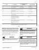
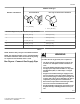
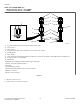
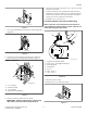
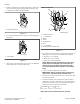
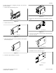
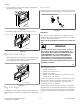
Table Of Contents
- Table of Contents
- Dimensions
- Installation
- Installer Checklist

Number of 90° Elbows
Weather Hood Type
Recommended Use Only for Short Run Installations
D673I_SVG
1
1
1. 4 in. [102 mm]
D802I_SVG
1
1. 2.5 in. [64 mm]
Maximum length of 4 in. [102 mm] diameter rigid metal duct.
0 65 feet [19.8 m] 55 feet [16.8 m]
1 55 feet [16.8 m] 47 feet [14.3 m]
2 47 feet [14.3 m] 41 feet [12.5 m]
3 36 feet [11.0 m] 30 feet [9.1 m]
4 28 feet [8.5 m] 22 feet [6.7 m]
Table 2
NOTE: Deduct 6 feet [1.8 m] for each additional elbow.
NOTE: The maximum length of a 4 in. [102 mm] diame-
ter flexible metal duct must not exceed 7.87 ft. [2.4 m],
as required to meet UL2158, clause 7.3.2.A.
Gas Dryers - Connect Gas Supply Pipe
WARNING
To reduce the risk of gas leaks, fire or explosion:
• The dryer must be connected to the type of gas
as shown on nameplate located in the door re-
cess.
• Use a new flexible stainless steel connector.
• Use pipe joint compound insoluble in L.P. (Lique-
fied Petroleum) Gas, or Teflon tape, on all pipe
threads.
• Purge air and sediment from gas supply line be-
fore connecting it to the dryer. Before tightening
the connection, purge remaining air from gas line
to dryer until odor of gas is detected. This step is
required to prevent gas valve contamination.
• Do not use an open flame to check for gas leaks.
Use a non-corrosive leak detection fluid.
• Any disassembly requiring the use of tools must
be performed by a suitably qualified service per-
son.
W316
Installation
©
Copyright, Alliance Laundry Systems LLC -
DO NOT COPY or TRANSMIT
13 Part No. D514320R3