Installation Instructions for Dryers Original Instructions Keep These Instructions for Future Reference. CAUTION: Read the instructions before using the machine. (If this machine changes ownership, this manual must accompany machine.) www.speedqueen.com Part No.
WARNING IMPORTANT: Purchaser must consult the local gas supplier for suggested instructions to be followed if the dryer user smells gas. The gas utility instructions plus the SAFETY and WARNING note directly above must be posted in a prominent location near the dryer for customer use. WARNING Risk of fire. Highly flammable material. WARNING W881 Read all instructions before using unit.
The following information applies to the state of Massachusetts, USA. • • • • This appliance can only be installed by a Massachusetts licensed plumber or gas fitter. This appliance must be installed with a 36 inch [910 mm] long flexible gas connector. A “T-Handle” type gas shut-off valve must be installed in the gas supply line to this appliance. This appliance must not be installed in a bedroom or bathroom. © Copyright, Alliance Laundry Systems LLC - DO NOT COPY or TRANSMIT 4 Part No.
Table of Contents Dimensions............................................................................................. 6 Installation............................................................................................. 8 Before You Start............................................................................................. 8 Supplies..................................................................................................... 8 Parts Included..........................................
Dimensions Dimensions Electric Dryers A 22.38 in. [569 mm] B 8.0 in. [203 mm] C * 36 in. [914 mm] D (to controls) Electronic Control: *41.25 in. [1048 mm] Knob Control: *40.75 [1035 mm] E * 42.75 in. [1086 mm] F 15.4 in. [391 mm] G * 15.44 in. [392 mm] H 26.875 in. [683 mm] I * 4.0 in. [102 mm] J 0.4 in. [11 mm] K * 4.5 in. [114 mm] L 28 in. [711 mm] M 23.5 in. [597 mm] NOTE: Exhaust openings are 4 inch [102 mm] metal ducting.
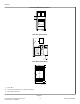
Dimensions Gas Dryers 1. 3/8 in. N.P.T. Gas Connection A 22.38 in. [569 mm] B 8.0 in. [203 mm] C * 36 in. [914 mm] D Electronic Control: *41.25 in. [1048 mm] Knob Control: *40.75 [1035 mm] E * 42.75 in. [1086 mm] F 15.4 in. [391 mm] G * 15.44 in. [392 mm] H * 2.8 in. [70 mm] I 2.3 in. [60 mm] J 26.875 in. [683 mm] K * 4 in. [102 mm] L 0.4 in. [10 mm] M * 4.5 in. [114 mm] N 28 in. [711 mm] O 23.5 in. [597 mm] NOTE: Exhaust openings are 4 inch [102 mm] metal ducting.
Installation Installation Before You Start • • Supplies Order of Installation Steps For most installations, the basic supplies you will need are: 1 2 3 1. Position and level the dryer. 2. Connect dryer to exhaust system. 3. For gas models only, connect the gas supply pipe. Check for gas leaks. 4. For electric models only, connect the electrical cord. 5. Reverse the door, if desired. 6. Wipe out the inside of the dryer. 7. Plug in the dryer. 8. Recheck steps. 9.
Installation 1. Dryer Base 2. Level 3. Leveling Leg Figure 2 © Copyright, Alliance Laundry Systems LLC - DO NOT COPY or TRANSMIT 9 Part No.
Installation Front View (Without Closet Door) B A A DRY2663N_SVG Side View (Closet Door) Front View (Closet Door) F 2 (G) F DRY2637N_SVG 1. Closet Door 2. Centered Air Openings (G) (2 Openings minimum) 3. Outer Wall of Enclosure Figure 3 © Copyright, Alliance Laundry Systems LLC - DO NOT COPY or TRANSMIT 10 Part No.
Installation Area Free Standing/Alcove Installation Description Closet Installation A* Dryer sides and rear clearance 0 in. [0 mm] 0 in. [0 mm] B Dryer top clearance 12.25 in. [305 mm] 12.25 in. [305 mm] C Dryer front clearance Not Applicable 2 in. [51 mm] D Exhaust duct clearance to com- 2 in. [51 mm] bustible material 2 in. [51 mm] E Weather hood to ground clearance 12 in. [305 mm] 12 in. [305 mm] F Distance from floor or ceiling to air opening edge Not Applicable 3 in.
Installation • WARNING • To reduce the risk of fire, DO NOT use plastic or thin foil ducting to exhaust the dryer. W354 • • • WARNING To reduce the risk of fire, the exhaust duct and weather hood MUST be fabricated of a material that will not support combustion. Rigid or flexible metal pipe is recommended for a clothes dryer. W048 • • • • Dryer exhaust duct MUST NOT terminate under mobile home. Exhaust duct must not be connected to any other duct, vent, or chimney.
Installation Weather Hood Type Number of 90° Elbows Recommended Use Only for Short Run Installations 1 1 D673I_SVG 1. 4 in. [102 mm] 1 D802I_SVG 1. 2.5 in. [64 mm] Maximum length of 4 in. [102 mm] diameter rigid metal duct. 0 65 feet [19.8 m] 55 feet [16.8 m] 1 55 feet [16.8 m] 47 feet [14.3 m] 2 47 feet [14.3 m] 41 feet [12.5 m] 3 36 feet [11.0 m] 30 feet [9.1 m] 4 28 feet [8.5 m] 22 feet [6.7 m] Table 2 NOTE: Deduct 6 feet [1.8 m] for each additional elbow.
Installation NOTE: When connecting to a gas line, an equipment shut-off valve in accordance with the National Fuel Gas Code, ANSI Z223.1/NFPA 54 and the Natural Gas and Propane Installation Code, CSA B149.1 must be installed within 6 feet [1.8 m] of the dryer. An 1/8 in. NPT pipe plug must be installed as shown for checking inlet pressure. Refer to Figure 5 . 1. Make certain your dryer is equipped for use with the type of gas in your laundry room.
Installation L.P. (Liquefied Petroleum) Gas, 2500 Btu/ft.3 [93.1 MJ/m3], service must be supplied at 10 ± 1.5 inch water column pressure. WARNING For proper operation at altitudes above 3000 feet [915 m] the L.P. gas valve spud orifice size must be reduced to ensure complete combustion. Refer to Table 4 . Improper connection of the equipment-grounding conductor can result in a risk of electric shock.
Installation NOTE: Use COPPER WIRE only. Shorter than 15 ft. (4.5 m) – use 10 AWG Longer than 15 ft. (4.5 m) – use 8 AWG 6 7 8 1 9 14 4 10 5 11 2 2 12 13 3 16 L1 L2 15 L1 L2 D816I_SVG 1. A typical 30-Amp Three-Wire Receptacle NEMA Type 10-30R 2. 120 ± 12 V.A.C. 3. 240 ± 12 V.A.C. 4. Intermediate Fuse Box (may be omitted if service entrance box is fused) 5. Wall Receptacle 6. Power Supply 7.
Installation 6. Secure the strain relief to the power cord, or wires, where they enter the dryer cabinet. 7. Check the continuity of the earth/ground connection before plugging the cord into an outlet. Use an acceptable indicating device connected to the center earth/ground pin of the plug and the green screw on the back of the cabinet. 8. Reinstall access cover and screw.
Installation 3. Remove earth/ground screw from earth/ground to neutral wire and save for use in Step 5. Earth/ground to neutral wire will be attached to the neutral terminal in Step 6. 4-Wire Connection 8 1 7 2 1 3 6 DRY2468N_SVG 1. Earth/Ground Screw 4 5 DRY2482N_SVG Figure 12 1. 2. 3. 4. 5. 6. 7. 8. 4. Use a strain relief and insert end of power cord through power supply hole.
Installation The door on this dryer is completely reversible. To reverse door proceed as follows: 1. Remove four hinge attaching screws. D273P_SVG Figure 18 D675I_SVG 5. Remove door strike from door liner and reinstall on opposite side. Figure 15 2. Remove all nine screws. DRY1917N_SVG Figure 19 D272P_SVG 6. Insert liner under flange on bottom of door, then push top of door liner into place. Figure 16 3. Pull bottom of door liner out, then pull down, removing door liner from door panel.
Installation 8. Using screwdriver, remove two door plugs, and reinstall on opposite side of door opening. Plug In the Dryer This appliance is to be supplied through a residual current device (RCD) having a rated residual operating current not exceeding 30 mA. WARNING The appliance must not be supplied through an external switching device, such as a timer, or connected to a circuit that is regularly switched on and off by a utility. D317S_SVG Figure 22 9.
Installation • • • • Do not overload circuits. Do not use an adapter. Do not use an extension cord. Do not operate both a washer and gas dryer on the same circuit. Use separately fused 15 amp circuits. The dryer is designed to be operated on a separate branch, polarized, three-wire, effectively grounded, 120 Volt, 60 Hertz, AC (alternating current) circuit protected by a 15 Ampere fuse, equivalent fusetron or circuit breaker.
Installation Electric Dryers 1. Close the loading door and start the dryer in a heat setting (refer to the operation instructions). 2. After the dryer has operated for three minutes, the exhaust air or exhaust pipe should be warm. Gas Dryers IMPORTANT: This operation is to be conducted by qualified personnel only. 1. To view the burner flame, remove the lower front panel of the dryer. 2. Close the loading door and start the dryer in a heat setting (refer to the operation instructions).
Installer Checklist Installer Checklist Fast Track for Installing the Dryer 1 Position and Level the Dryer. 6 CHECK Wipe Out Inside of Dryer. CHECK DRY2634N_SVG 2 Connect Dryer Exhaust System. 7 CHECK Plug In the Dryer. Electric CHECK D275I_SVG1 Gas TLW2289N_SVG 3 GAS ONLY • • 8 Connect Gas Supply Pipe. Check for Gas Leaks. CHECK 4 CHECK ELECTRIC ONLY • Recheck Steps. 9 Connect Electrical Cord. CHECK Start and Run Dryer in Heat Setting to Verify Dryer is Heating.