Installation Instructions for Frontload Washers Original Instructions Keep These Instructions for Future Reference. (If this machine changes ownership, this manual must accompany machine.) www.speedqueen.com Part No.
Table of Contents Washer Dimensions................................................................................ 4 Installation............................................................................................. 5 Before You Start............................................................................................. 5 Tools..........................................................................................................5 Parts Included...............................................
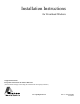
Washer Dimensions Washer Dimensions A D B C E J H I F G FLW2331N_SVG Figure 1 A 24.06 in. [611 mm] B 40.42 in. [1027 mm] C 32 in. [813 mm] D 39.61 in. [1006 mm] E* 14.6 in. [371 mm] F 26.875 in. [683 mm] G 2.04 in. [52 mm] H 27.73 in. [704 mm] I (with door closed) 1.59 in. [40 mm] J 13.1 in. [333 mm] * For ADA compliance turn legs out from base 0.5 inches. © Copyright, Alliance Laundry Systems LLC - DO NOT COPY or TRANSMIT 4 Part No.
Installation Installation Before You Start Parts Included Tools An accessories bag has been shipped inside your washer. It includes: For most installations, the basic tools you will need are: 1 • • • • • • 2 4 3 5 Order of Installation Steps " 16 9/ The proper order of steps must be followed to ensure correct installation. Refer to the list below when installing your unit. 1. Position washer near the installation area. 2. Remove the shipping materials. 3. Connect the fill hoses. 4.
Installation FLW2297N_SVG1 Figure 5 FLW2378N_SVG 6. Insert two plugs included in accessories bag into rear shipping bolt holes. Figure 3 2. Remove two 9/16 inch bolts and washers holding shipping brace to weight. 3. Remove two 9/16 inch bolts and washers holding shipping brace to washer base and remove brace. FLW2358N_SVG Figure 6 7. Replace front access panel. 8. Save all shipping materials. They must be reinstalled any time washer is moved more than four feet.
Installation mixing valve marked “H” and the blue color-coded hose from the cold faucet goes to the valve marked “C”. Refer to Figure Figure 7 . 6. Then, using a pliers, screw approximately 1/4 turn. Water Supply Requirements Water supply faucets must fit standard 3/4 inch [19 mm] female garden hose couplings. DO NOT USE SLIP-ON OR CLAMPON CONNECTIONS. IMPORTANT: DO NOT cross thread or overtighten couplings. This will cause them to leak. 7. Turn water on and check for leaks. 8.
Installation NOTE: End of drain hose must not be below 24 in. [610 mm]. Install the drain hose into the drain receptacle (standpipe, wall or laundry tub) following the instructions below. IMPORTANT: Drain receptacle must be capable of handling a minimum of 1-1/4 inch [32 mm] outside diameter drain hose. 1 2 Drain Flow Rate Flow Rate gallons per minute [liters per minute] Drain Height 3 ft. [0.9 m] 8.6 [32.7] 5 ft. [1.5 m] 6.8 [25.9] 6 ft. [1.8 m] 6.0 [22.7] 7 ft. [2.1 m] 5.1 [19.5] 8 ft. [2.
Installation Position and Level the Washer 3 1 2 WARNING Washers elevated above floor level must be anchored to that elevated surface, base or platform. The material used to elevate the washer should also be anchored to the floor to ensure that the washer will not walk or that the washer can not be physically pulled, tipped or slid from its installed position. Failure to do so may result in conditions which can produce serious injury, death and/or property damage. 6 W306 4 1.
Installation Standard 120 Volt, 60 Hertz 3-Wire Effective Earth/ Ground Circuit WARNING To reduce the risk of fire, electric shock, serious injury or death, all wiring and protective earth/ground connections MUST conform with the latest edition of the National Electrical Code, ANSI/NFPA No. 70, and such local regulations as might apply.
Installation led and connected to a protective earth/ground in accordance with all local codes and ordinances. WARNING Improper connection of the equipment earth/ground conductor can result in a risk of electric shock. Check with a qualified electrician or service person if you are in doubt as to whether the unit is properly connected to a protective earth/ground.
Installer Checklist Installer Checklist Fast Track for Installing the Washer 1 Position Washer Near Installation Area. 5 CHECK Position and Level the Washer. CHECK FLW2312N_SVG1 2 Remove the Shipping Materials and Install Plugs. 6 CHECK Wipe Out Inside of Washer. CHECK FLW2316N_SVG FLW2359N_SVG 3 Connect Fill Hoses. CHECK 7 COLD HOT Plug In the Washer. CHECK FLW2304N_SVG D254I_SVG 4 Connect Drain Hose to Drain Receptacle.