Installation Instructions for Dryers Original Instructions Keep These Instructions for Future Reference. CAUTION: Read the instructions before using the machine. (If this machine changes ownership, this manual must accompany machine.) www.alliancelaundry.com Part No.
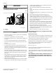
WARNING WARNING WARNING FOR YOUR SAFETY, the information in this manual must be followed to minimize the risk of fire or explosion or to prevent property damage, personal injury or death. • • W033 • WARNING • • • Do not store or use gasoline or other flammable vapors and liquids in the vicinity of this or any other appliance. WHAT TO DO IF YOU SMELL GAS: • Do not try to light any appliance. • Do not touch any electrical switch; do not use any phone in your building.
Table of Contents ...............................................................................................................3 Dimensions............................................................................................. 5 Installation............................................................................................. 7 Before You Start............................................................................................. 7 Supplies...............................................
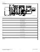
Dimensions Dimensions Electric Models A E B K M L F D C I G J H DRY2283N_SVG A 22.38 in. [569 mm] B 8.0 in. [203 mm] C *36 in. [914 mm] D *40.25 in. [1022 mm] E *43 in. [1092 mm] F 15.4 in. [391 mm] G * 15.44 in. [392 mm] H 26.9 in. [683 mm] I *4.0 in. [102 mm] J 0.4 in. [11 mm] K * 4.5 in. [114 mm] L 28 in. [711 mm] M 23.5 in. [597 mm] NOTE: Exhaust openings are 4 inch [102 mm] metal ducting.
Dimensions Gas Models A E B M O N F D G C K L J H I DRY2284N_SVG 1. 3/8 in. N.P.T. Gas Connection A 22.38 in. [569 mm] B 8.0 in. [203 mm] C *36 in. [914 mm] D *40.25 in. [1022 mm] E *43 in. [1092 mm] F 15.4 in. [391 mm] G *15.44 in. [392 mm] H *2.8 in. [70 mm] I 2.3 in. [60 mm] J 26.9 in. [683 mm] K *4 in. [102 mm] L 0.4 in. [11 mm] M *4.5 in. [114 mm] N 28 in. [711 mm] O 23.5 in. [597 mm] NOTE: Exhaust openings are 4 inch [102 mm] metal ducting.
Installation Installation Before You Start 6. Plug in the dryer. 7. Recheck steps. 8. Check heat source. Supplies For most installations, the basic supplies you will need are: Position and Level the Dryer 2 1 1. Install dryer before washer. This allows room for attaching exhaust duct. 2. Select a location with a solid floor. Dryers installed in residential garages must be elevated 18 inches [457 mm] above the floor.
Installation Front View (Without Closet Door) B A A DRY2663N_SVG Side View (Closet Door) 1 D E A C H 3 DRY2664N_SVG Front View (Closet Door) F 2 (G) F DRY2637N_SVG 1. Closet Door 2. Centered Air Openings (G) (2 Openings minimum) 3. Outer Wall of Enclosure Figure 3 © Copyright, Alliance Laundry Systems LLC - DO NOT COPY or TRANSMIT 8 Part No.
Installation Area Free Standing/Alcove Installation Description Closet Installation A* Dryer sides and rear clearance 0 in. [0 mm] 0 in. [0 mm] B Dryer top clearance 12 in. [305 mm] 12 in. [305 mm] C Dryer front clearance Not Applicable 2 in. [51 mm] D Exhaust duct clearance to com- 2 in. [51 mm] bustible material 2 in. [51 mm] E Weather hood to ground clearance 12 in. [305 mm] 12 in. [305 mm] F Distance from floor or ceiling to air opening edge Not Applicable 3 in.
Installation • WARNING • To reduce the risk of fire, DO NOT use plastic or thin foil ducting to exhaust the dryer. W354 • • • • • 1 2 • DRY1915N_SVG 1. Correct 2. Incorrect • Figure 4 • • • • • • • • • • DO NOT use plastic, thin foil or type B ducting. Rigid metal duct is recommended. Locate dryer so exhaust duct is as short as possible. Be certain old exhaust ducts are cleaned before installing your new dryer. Use 4 inch [102 mm] diameter rigid or flexible metal duct.
Installation Weather Hood Type Number of 90° Elbows Recommended Use Only for Short Run Installations 1 1 D673I_SVG 1. 4 in. [102 mm] 1 D802I_SVG 1. 2.5 in. [64 mm] Maximum length of 4 in. [102 mm] diameter rigid metal duct. 0 65 feet [19.8 m] 55 feet [16.8 m] 1 55 feet [16.8 m] 47 feet [14.3 m] 2 47 feet [14.3 m] 41 feet [12.5 m] 3 36 feet [11.0 m] 30 feet [9.1 m] 4 28 feet [8.5 m] 22 feet [6.7 m] Table 2 NOTE: Deduct 6 feet [1.8 m] for each additional elbow.
Installation Gas Dryers - Connect Gas Supply Pipe Natural Gas Altitude Adjustments WARNING Altitude Orifice Size To reduce the risk of gas leaks, fire or explosion: • • • • • • The dryer must be connected to the type of gas as shown on nameplate located in the door recess. Use a new flexible stainless steel connector. Use pipe joint compound insoluble in L.P. (Liquefied Petroleum) Gas, or Teflon tape, on all pipe threads.
Installation L.P. Altitude Adjustments 1 Altitude Orifice Size feet [m] No. 5 2 inches [mm] 3000 [915] 55 0.0520 [1.32] 58755 8000 [2440] 56 0.0465 [1.18] D503786 3 4 Table 4 D233I_SVG 1. New Stainless Steel Flexible Connector – (Use design CSA certified connector) Use only if allowed by local codes 2. 1/8 in. NPT Pipe Plug 3. Equipment Shut-Off Valve 4. Black Iron Pipe: Shorter than 20 ft. [6.1 m] – Use 3/8 in. [9.5 mm] pipe. Longer than 20 ft. [6.1 m] – Use 1/2 in. [12.7 mm] pipe. 5.
Installation ing element) listed on the nameplate. Do not connect dryer to 110, 115, or 120 Volt circuit. Heating elements are available for field installation in dryers which are to be connected to electrical service of different voltage than that listed on serial plate, such as 208 Volt. NOTE: Branch circuit wire size requirements to laundry room outlet are shown in table below. Wire Length Wire Less than 15 ft. [4.5 m] Listed No. 10 AWG Copper wire only Longer than 15 ft. [4.5 m] Listed No.
Installation 6 7 8 1 9 14 4 10 5 11 2 2 12 13 3 16 L1 L2 15 L1 L2 D816I_SVG 1. A typical 30-Amp Three-Wire Receptacle NEMA Type 10-30R 2. 120 ± 12 V.A.C. 3. 240 ± 12 V.A.C. 4. Intermediate Fuse Box (may be omitted if service entrance box is fused) 5. Wall Receptacle 6. Power Supply 7. 3-Wire Earth/Ground Neutral 120/240 Volt, 60 Hertz AC 1 Phase Service Entrance Switch Box (Refer to NOTE above) 8. 30 Ampere Fuses or Circuit Breaker 9. Neutral Wire 10.
Installation 3. Use a strain relief and insert end of power cord through power supply hole. 2 1 3 4 7 7 6 Figure 8 7 5 7 D696I_SVG 4. Use the three screws from the accessories bag to attach the power cord wires to the terminal block. Refer to Figure 9 . 1 DRY2016N_SVG 1. 2. 3. 4. 5. 6. 7. 2 3 D286I_SVG 1. "L1" Terminal 2. Neutral Terminal 3. "L2" Terminal Typical Four-Wire Receptacle Power Cord – Not Supplied with Dryer Strain Relief Nut Strain Relief 0 V.A.C. 240 ± 12 V.A.C. 120 ± 12 V.
Installation 1 7 6 5 D696I_SVG 2 4 Figure 12 4. Remove earth/ground screw save for use in Step 6. Remove wire and use in Step 7. 3 1 DRY1920N_SVG 1. 2. 3. 4. 5. 6. 7. D697_SVGI 1. Ground Screw Figure 15 Figure 13 5. Use a strain relief and insert end of power cord through power supply hole. White “L2” Terminal Black Green Red Neutral Terminal “L1” Terminal 7. Use the three screws from the accessories bag to attach the remaining power cord wires to the terminal block as follows: a.
Installation 5. Remove door strike from door liner and reinstall on opposite side. D675I_SVG DRY1917N_SVG Figure 16 2. Remove all nine screws. Figure 20 6. Insert liner under flange on bottom of door, then push top of door liner into place. B A D272P_SVG DRY1918N_SVG Figure 17 3. Pull bottom of door liner out, then pull down, removing door liner from door panel. Figure 21 7. Reinstall nine screws removed in Step 2. B A DRY1916N_SVG DRY1919N_SVG Figure 18 Figure 22 4.
Installation Connect to 30 Amp circuit. D275I_SVG2 D620I_SVG Figure 26 Figure 23 9. Reinstall four hinge attaching screws, removed in Step 1. Gas Dryers Dryer requires 120 Volt, 60 Hertz electrical supply and comes equipped with a 3-prong grounding plug. Refer to serial plate for specific electrical requirements. NOTE: The wiring diagram is located in the control hood.
Installation is equipped with a cord having an equipment-grounding conductor and a 3 prong grounding plug. The three-prong grounding plug on the power cord should be plugged directly into a polarized three-slot effectively grounded receptacle rated 110/120 Volts AC (alternating current) 15 Amps. Plug cord into separately fused 15 Amp circuit.
Installation 2. Close the loading door and start the dryer in a heat setting (refer to the operation instructions). The dryer will start, the igniter will glow red and the main burner will ignite. IMPORTANT: If all air is not purged out of gas line, gas igniter may go off before gas is ignited. If this happens, after approximately two minutes igniter will again attempt gas ignition. IMPORTANT: If igniter does not light, make sure gas is turned on. 3.
Installer Checklist Installer Checklist Fast Track for Installing the Dryer 1 Position and Level the Dryer. 6 CHECK Wipe Out Inside of Dryer. CHECK DRY2634N_SVG 2 Connect Dryer Exhaust System. D618I_SVG1 7 CHECK Plug In the Dryer. Electric CHECK DRY1915N_SVG1 D275I_SVG1 Gas D254I_SVG 3 GAS ONLY • • 8 Recheck Steps. Connect Gas Supply Pipe. Check for Gas Leaks. D258I_SVG1 CHECK 4 CHECK ELECTRIC ONLY • 9 Check Heat Source Connect Electrical Cord.