Installation Instructions for Stacked Dryers Original Instructions Keep These Instructions for Future Reference. CAUTION: Read the instructions before using the machine. (If this machine changes ownership, this manual must accompany machine.) www.alliancelaundry.com Part No.
WARNING IMPORTANT: Purchaser must consult the local gas supplier for suggested instructions to be followed if the dryer user smells gas. The gas utility instructions plus the SAFETY and WARNING note directly above must be posted in a prominent location near the dryer for customer use. WARNING Risk of fire. Highly flammable material. WARNING W881 Read all instructions before using unit.
The following information applies to the state of Massachusetts, USA. • • • • This appliance can only be installed by a Massachusetts licensed plumber or gas fitter. This appliance must be installed with a 36 inch [910 mm] long flexible gas connector. A “T-Handle” type gas shut-off valve must be installed in the gas supply line to this appliance. This appliance must not be installed in a bedroom or bathroom. © Copyright, Alliance Laundry Systems LLC - DO NOT COPY or TRANSMIT 4 Part No.
Table of Contents Dimensions............................................................................................. 6 Installation............................................................................................. 9 Before You Start............................................................................................. 9 Supplies..................................................................................................... 9 Position and Level the Dryer............................
Dimensions Dimensions Electric Dryers A K E B G M F H C D I J L DRY2598N_SVG Figure 1 A 23.5 in. [597 mm] B 8.375 in. [213 mm] C 28 in. [711 mm] D .4 in. [11 mm] E 8 in. [203 mm] F 46.62 in. [1184 mm] G *78.17 in. [1986 mm] H *4 in. [102 mm] I *4.5 in. [114 mm] J 26.875 in. [683 mm] K 15.4 in. [391 mm] L *15.44 in. [392 mm] M *39.13 in. [994 mm] NOTE: Exhaust openings are 4 inch [102 mm] metal ducting.
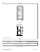
Dimensions Gas Dryers A L E B G M F P H N K C D I J O 1 DRY2599N_SVG 1. 3/8 in. N.P.T. Gas Connection Figure 2 A 23.5 in. [597 mm] B 8.375 in. [213 mm] C 28 in. [711 mm] D 0.4 in. [11 mm] E 8 in. [203 mm] F 46.62 in. [1184 mm] G *78.17 in. [1986 mm] H *4 in. [102 mm] I *4.5 in. [114 mm] J 26.875 in. [683 mm] K 2.3 in. [60 mm] L 15.4 in. [391 mm] M *44.87 in. [1140 mm] N *2.8 in. [70 mm] O *15.44 in. [392 mm] P *39.13 in. [994 mm] Table continues...
Dimensions NOTE: Exhaust openings are 4 inch [102 mm] metal ducting. * With leveling legs turned into base. NOTE: Gas models cannot be vented out left side of cabinet because of burner housing. IMPORTANT: The dryer should have sufficient clearance around it for needed ventilation and for the ease of installation and servicing. For maximum drying performance, we recommend that more clearance be allowed around the dryer than the clearances that are listed throughout this manual.
Installation Installation Before You Start Position and Level the Dryer Supplies 1. Select a location with a solid floor. Dryers installed in residential garages must be elevated 18 inches [457 mm] above the floor. No other fuel burning appliance should be installed in the same closet with the dryer. For most installations, the basic supplies you will need are: 1 2 3 4 The dryer must not be installed or stored in an area where it will be exposed to water and/or weather.
Installation Front View A A DRY2667N_SVG Side View B D C E E 1 DRY2668N_SVG 1. Outer Wall of Enclosure Figure 5 Area Description Free Standing/Alcove Installation A Dryer sides 0 in. [0 mm] B Dryer top (rear 24 in. [610 mm]) 12 in. [305 mm] Table 1 continues... © Copyright, Alliance Laundry Systems LLC - DO NOT COPY or TRANSMIT 10 Part No.
Installation Area Description Free Standing/Alcove Installation C* Dryer rear 4 in. [102 mm] D Dryer Top (front 4 in. [201 mm]) 0.5 in. [13 mm] E Exhaust duct clearance to combustible ma- 2 in. [51 mm] terial * Rear clearance is minimum. 6 inches [152 mm] is recommended when venting through rear of unit. Table 1 NOTE: For new installations, it is suggested to locate top of wall vent 42 inches (106.7 cm) above floor to make venting easier to connect.
Installation IMPORTANT: Installing in-line filters or lint collectors will cause increased static pressure. Failure to maintain the secondary lint system will decrease dryer efficiency and will void machine warranty. • • • • 1 2 DRY2540N_SVG 1. Correct 2. Incorrect Figure 6 • • • • • • • • • • • • • • • DO NOT use plastic, thin foil or type B ducting. Rigid metal duct is recommended. Locate dryer so exhaust duct is as short as possible.
Installation Weather Hood Type Number of 90° Elbows Recommended Use Only for Short Run Installations 1 1 D673I_SVG 1. 4 in. [102 mm] 1 D802I_SVG 1. 2.5 in. [64 mm] Maximum length of 4 in. [102 mm] diameter rigid metal duct. 0 65 feet [19.8 m] 55 feet [16.8 m] 1 55 feet [16.8 m] 47 feet [14.3 m] 2 47 feet [14.3 m] 41 feet [12.5 m] 3 36 feet [11.0 m] 30 feet [9.1 m] 4 28 feet [8.5 m] 22 feet [6.7 m] Table 2 NOTE: Deduct 6 feet [1.8 m] for each additional elbow.
Installation NOTE: When connecting to a gas line, an equipment shut-off valve in accordance with the National Fuel Gas Code, ANSI Z223.1/NFPA 54 and the Natural Gas and Propane Installation Code, CSA B149.1 must be installed within 6 feet [1.8 m] of the dryer. An 1/8 in. NPT pipe plug must be installed as shown for checking inlet pressure. Refer to Figure 7 . 1. Make certain your dryer is equipped for use with the type of gas in your laundry room.
Installation For proper operation at altitudes above 3000 feet [915 m] the L.P. gas valve spud orifice size must be reduced to ensure complete combustion. Refer to Table 4 . WARNING Improper connection of the equipment earth/ground conductor can result in a risk of electric shock. Check with a qualified electrician or service person if you are in doubt as to whether the dryer is properly connected to a protective earth/ground. L.P. Altitude Adjustments Altitude feet [m] Orifice Size No.
Installation NOTE: Use COPPER WIRE only. Shorter than 15 ft. (4.5 m) – use 10 AWG Longer than 15 ft. (4.5 m) – use 8 AWG 6 7 8 1 9 14 4 10 5 11 2 2 12 13 3 16 L1 L2 15 L1 L2 D816I_SVG 1. A typical 30-Amp Three-Wire Receptacle NEMA Type 10-30R 2. 120 ± 12 V.A.C. 3. 240 ± 12 V.A.C. 4. Intermediate Fuse Box (may be omitted if service entrance box is fused) 5. Wall Receptacle 6. Power Supply 7.
Installation 6. Secure the strain relief to the power cord, or wires, where they enter the dryer cabinet. 7. Check the continuity of the earth/ground connection before plugging the cord into an outlet. Use an acceptable indicating device connected to the center earth/ground pin of the plug and the green screw on the back of the cabinet. 8. Reinstall access cover and screw.
Installation 3. Remove earth/ground screw from earth/ground to neutral wire and save for use in Step 5. Earth/ground to neutral wire will be attached to the neutral terminal in Step 6. 4-Wire Connection 8 1 7 2 1 3 6 DRY2468N_SVG 1. Earth/Ground Screw 4 5 DRY2482N_SVG Figure 14 1. 2. 3. 4. 5. 6. 7. 8. 4. Use a strain relief and insert end of power cord through power supply hole.
Installation The door on this dryer is completely reversible. To reverse door proceed as follows: 1. Remove four hinge attaching screws. D273P_SVG Figure 20 D675I_SVG 5. Remove door strike from door liner and reinstall on opposite side. Figure 17 2. Remove all nine screws. DRY1917N_SVG Figure 21 D272P_SVG 6. Insert liner under flange on bottom of door, then push top of door liner into place. Figure 18 3. Pull bottom of door liner out, then pull down, removing door liner from door panel.
Installation 8. Using screwdriver, remove two door plugs, and reinstall on opposite side of door opening. D317S_SVG Figure 24 9. Reinstall four hinge attaching screws, removed in Step 1. DRY2601N_SVG Figure 26 Plug In the Dryer D606I_SVG Figure 25 Wipe Out Inside of Dryer Before using dryer for the first time, use an all-purpose cleaner, or a detergent and water solution, and a damp cloth to remove shipping dust from inside dryer drum.
Installation Plug Cord Into Separately Fused 15 Amp Circuit WARNING To reduce the risk of fire, electric shock, serious injury or death, all wiring and grounding MUST conform with the latest edition of the National Electrical Code, ANSI/NFPA 70, or the Canadian Electrical Code, CSA C22.1, and such local regulations as might apply. It is the customer’s responsibility to have the wiring and fuses installed by a qualified electrician to make sure adequate electrical power is available to the dryer.
Installation 2. After the dryer has operated for three minutes, the exhaust air or exhaust pipe should be warm. WARNING This unit is equipped with a three-prong (earth/ ground) plug for your protection against shock hazard and should be plugged directly into a protective earth/ ground three-prong receptacle. Do not cut or remove the earth/ground prong from this plug. W823 WARNING Improper connection of the equipment earth/ground conductor can result in a risk of electric shock.
Installation Shut-off Valve Only Applicable on Certain Models 5 1 6 4 3 2 DRY2753N_SVG 1. 2. 3. 4. 5. 6. Air Shutter Lockscrew Air Shutter 1/8 in. [3.1 mm] Pipe Plug (For checking manifold pressure) Shut-off Valve Open Position Shut-off Valve Closed Position Shut-off Valve Handle Figure 29 © Copyright, Alliance Laundry Systems LLC - DO NOT COPY or TRANSMIT 23 Part No.
Installer Checklist Installer Checklist Fast Track for Installing the Dryer 1 Position and Level the Dryer. 5 CHECK Wipe Out Inside of Dryer. CHECK DRY2601N_SVG1 DRY2634N_SVG 2 Connect Dryer Exhaust System. 6 CHECK Plug In the Dryer. Electric CHECK DRY2540N_SVG1 D275I_SVG1 Gas D254I_SVG 3 GAS ONLY • Connect Gas Supply Pipe. • Check for Gas Leaks. 7 CHECK Recheck Steps. CHECK D233I_SVG1 4 ELECTRIC ONLY Connect Electrical Cord.