Installation Instructions for Stacked Washer/Dryers Original Instructions Keep These Instructions for Future Reference. CAUTION: Read the instructions before using the machine. (If this machine changes ownership, this manual must accompany machine.) www.alliancelaundry.com Part No.
WARNING IMPORTANT: Purchaser must consult the local gas supplier for suggested instructions to be followed if the dryer user smells gas. The gas utility instructions plus the SAFETY and WARNING note directly above must be posted in a prominent location near the dryer for customer use. WARNING Risk of fire. Highly flammable material. WARNING W881 Read all instructions before using unit.
The following information applies to the state of Massachusetts, USA. • • • • This appliance can only be installed by a Massachusetts licensed plumber or gas fitter. This appliance must be installed with a 36 inch [910 mm] long flexible gas connector. A “T-Handle” type gas shut-off valve must be installed in the gas supply line to this appliance. This appliance must not be installed in a bedroom or bathroom. © Copyright, Alliance Laundry Systems LLC - DO NOT COPY or TRANSMIT 4 Part No.
Table of Contents Dimensions............................................................................................. 6 Installation............................................................................................. 9 Before You Start............................................................................................. 9 Tools..........................................................................................................9 Order of Installation Steps............................
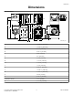
Dimensions Dimensions Electric Models C G F D A E L B H M J Q O P K N I SWD1003N_SVG A * 66.06 in. [1678 mm] B * 56.97 in. [1447 mm] C 23.5 in. [597 mm] D 8.375 in. [213 mm] E 24 in. [610 mm] F 8 in. [203 mm] G 15.4 in. [391 mm] H * 36.9 in. [938 mm] I ** * 14.6 in. [371 mm] J * 32 in. [813 mm] K 26.875 in. [683 mm] L * 46.62 in. [1184 mm] M * 78.17 in. [1986 mm] N 2.04 in. [52 mm] O 27.73 in. [704 mm] P (with door closed) 1.5 in. [38 mm] Q * 13.1 in.
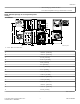
Dimensions * With leveling legs turned into base. ** For ADA compliance turn legs out from base 0.5 inches. NOTE: Exhaust openings are 4 inch [102 mm] metal ducting. Gas Models C G F 1 D E H O A B I N L K S Q R M P J SWD1004N_SVG 1. 3/8 in. NPT Gas Connection A *66.06 in. [1678 mm] B *56.97 in. [1447 mm] C 23.5 in. [597 mm] D 8.375 in. [213 mm] E 24 in. [610 mm] F 8 in. [203 mm] G 15.4 in. [391 mm] H 2.3 in. [59 mm] I *36.9 in. [938 mm] J ** *14.6 in. [371 mm] K *44.
Dimensions Q 27.73 in. [704 mm] R (with door closed) 1.5 in. [38 mm] S *13.1 in. [333 mm] * With leveling legs turned into base. ** For ADA compliance turn legs out from base 0.5 inches. NOTE: Exhaust openings are 4 inch [102 mm] metal ducting. © Copyright, Alliance Laundry Systems LLC - DO NOT COPY or TRANSMIT 8 Part No.
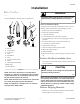
Installation Installation Before You Start WARNING Tools Any disassembly requiring the use of tools must be performed by a suitably qualified service person. For most installations, the basic tools you will need are: 1 2 3 4 W299 5 Order of Installation Steps The proper order of steps must be followed to ensure correct installation. Refer to the list below when installing your unit. 6 1. 2. 3. 4. 5. Position unit near area of installation. Remove the shipping materials. Connect the fill hoses.
Installation FLW2297N_SVG1 Figure 4 FLW2378N_SVG Figure 2 6. Insert two plugs included in accessories bag into rear shipping bolt holes. 2. Remove two 9/16 inch bolts and washers holding shipping brace to weight. 3. Remove two 9/16 inch bolts and washers holding shipping brace to washer base and remove brace. FLW2358N_SVG Figure 5 7. Replace front access panel. 8. Save all shipping materials. They must be reinstalled any time washer is moved more than four feet.
Installation Water Supply Requirements Water supply faucets must fit standard 3/4 inch [19 mm] female garden hose couplings. DO NOT USE SLIP-ON OR CLAMPON CONNECTIONS. 6. If leaks are found, retighten the hose couplings. 7. Continue tightening and rechecking until no leaks are found. NOTE: Water supply faucets should be readily accessible to permit turning them off when washer is not being used. HOT 6 1. 2. 3. 4. 5. 6.
Installation Standpipe Installation 1 1. Place the drain hose into the standpipe. 2. Remove the beaded tie-down strap from accessories bag and place around standpipe and drain hose. Refer to Figure 8 . a. Insert the end of the beaded strap into the larger hole found on the end of the strap. b. Tighten to desired fit. c. Lock strap in place by pulling beaded strap into the tapered smaller opening of the beaded strap end. A distinct snap noise should be heard once the strap is properly seated. d.
Installation Gas Dryers - Connect Gas Supply Pipe 1 WARNING 2 To reduce the risk of gas leaks, fire or explosion: • • • 3 H023i_SVG • 1. Drain Hose 2. Beaded Strap (tape if necessary) 3. Fill Hoses Figure 9 • Laundry Tub Installation • For this type of installation, the drain hose MUST be secured to the stationary tub to prevent hose from disloding during use. Refer to Figure 10 . Use the beaded strap (supplied in accessories bag) to secure hose.
Installation Natural Gas Altitude Adjustments Altitude feet [m] 1 Orifice Size No. inches [mm] Part No. 5 2 8000 [2440] 45 0.0820 [2.08] D503779 9000 [2740] 46 0.0810 [2.06] D503780 10,000 [3050] 47 0.0785 [1.99] D503781 3 4 Table 1 2. Remove the shipping cap from the gas connection at the rear of the dryer. Make sure you do not damage the pipe threads when removing the cap. D233I_SVG 1.
Installation L.P. Altitude Adjustments Altitude feet [m] Orifice Size No. inches [mm] Part No. 3000 [915] 55 0.0520 [1.32] 58755 8000 [2440] 56 0.0465 [1.18] D503786 Table 2 Electric Dryer Only - Connect Electrical Plug The dryer has its own terminal block that must be connected to a separate branch, 60 Hertz, single phase circuit, AC (alternating current) circuit, fused at 30 Amperes (the circuit must be fused on both sides of the line).
Installation 6 7 8 1 9 14 4 10 5 11 2 2 12 13 3 16 L1 L2 15 L1 L2 D816I_SVG 1. A typical 30-Amp Three-Wire Receptacle NEMA Type 10-30R 2. 120 ± 12 V.A.C. 3. 240 ± 12 V.A.C. 4. Intermediate Fuse Box (may be omitted if service entrance box is fused) 5. Wall Receptacle 6. Power Supply 7. 3-Wire Earth/Ground Neutral 120/240 Volt, 60 Hertz AC 1 Phase Service Entrance Switch Box (Refer to NOTE above) 8. 30 Ampere Fuses or Circuit Breaker 9. Neutral Wire 10.
Installation 3. Use a strain relief and insert end of power cord through power supply hole. 2 1 3 4 7 7 6 Figure 14 7 5 7 D696I_SVG 4. Use the three screws from the accessories bag to attach the power cord wires to the terminal block. Refer to Figure 15 . DRY2016N_SVG 3-Wire Connection 1. 2. 3. 4. 5. 6. 7. 1 2 Typical Four-Wire Receptacle Power Cord – Not Supplied with Dryer Strain Relief Nut Strain Relief 0 V.A.C. 240 ± 12 V.A.C. 120 ± 12 V.A.C. Figure 16 4 3 1.
Installation 4-Wire Connection 8 1 7 1 2 DRY2468N_SVG 1. Earth/Ground Screw 3 6 Figure 18 DRY2482N_SVG 1. 2. 3. 4. 5. 6. 7. 8. DRY2469N_SVG 1. Strain Relief Figure 19 5. Attach power cord earth/ground (green) wire to rear bulkhead using earth/ground screw removed in Step 3. 4 5 4. Use a strain relief and insert end of power cord through power supply hole. Neutral Terminal “L2” Terminal Black White Earth/Ground Red “L1” Terminal Earth/Ground to Neutral Wire Figure 20 6.
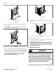
Installation Connect Dryer Exhaust System WARNING To reduce the risk of fire and combustion gas accumulation the dryer MUST be exhausted to the outdoors. W604 WARNING To reduce the risk of fire and the accumulation of combustion gases, DO NOT exhaust dryer air into a window well, gas vent, chimney or enclosed, unventilated area, such as an attic, wall, ceiling, crawl space under a building or concealed space of a building. 1 SWD997N_SVG 1. Correct 2.
Installation • Exhausting dryer in hard-to-reach locations can be done by installing 521P3 Flexible Metal Vent Kit (available as optional equipment at extra cost). Sufficient make-up air must be supplied to replace the air exhausted by the dryer. The free area of any opening for outside air must be at least 40 in.2 [25806 mm2] per unit. Failure to exhaust dryer properly will void warranty. A dryer will dissipate 60 Btu/ft2 [681,392 J/m2] of surface area exposed to the conditioned air.
Installation Position and Level the Unit Dryer and Exhaust Duct Clearances WARNING Area Units elevated above floor level must be anchored to that elevated surface, base or platform. The material used to elevate the unit should also be anchored to the floor to ensure that the unit will not walk or that the unit can not be physically pulled, tipped or slid from its installed position. Failure to do so may result in conditions which can produce serious injury, death and/or property damage. E 2. 3.
Installation 1 6 5 2 4 SWD1013N_SVG 3 SWD1029N_SVG 1. 2. 3. 4. 5. 6. Level Wood Block Rubber Foot Leveling Leg Locknut Unit Base Figure 24 Plug In the Washer and Dryer Electric Dryer Connect the dryer to an electrical power source. Refer to Connect Electrical Plug section for information on connecting power cord.
Installation Plug Cord Into Separately Fused 15 Amp Circuit WARNING To reduce the risk of fire, electric shock, serious injury or death, all wiring and grounding MUST conform with the latest edition of the National Electrical Code, ANSI/NFPA 70, or the Canadian Electrical Code, CSA C22.1, and such local regulations as might apply. It is the customer’s responsibility to have the wiring and fuses installed by a qualified electrician to make sure adequate electrical power is available to the dryer.
Installation WARNING WARNING This unit is equipped with a three-prong (earth/ ground) plug for your protection against shock hazard and should be plugged directly into a protective earth/ ground three-prong receptacle. Do not cut or remove the earth/ground prong from this plug. To reduce the risk of fire, electric shock, serious injury or death, all wiring and protective earth/ground connections MUST conform with the latest edition of the National Electrical Code, ANSI/NFPA No.
Installation Standard 120 Volt, 60 Hertz 3-Wire Effective Earth/ Ground Circuit 2 WARNING Improper connection of the equipment earth/ground conductor can result in a risk of electric shock. Check with a qualified electrician or service person if you are in doubt as to whether the unit is properly connected to a protective earth/ground.
Installation Gas Dryers 1 IMPORTANT: This operation is to be conducted by qualified personnel only. 1. To view the burner flame, remove the lower front panel of the dryer. 2. Close the loading door and start the dryer in a heat setting (refer to the operation instructions). The dryer will start, the igniter will glow red and the main burner will ignite. IMPORTANT: If all air is not purged out of gas line, gas igniter may go off before gas is ignited.
Installer Checklist Installer Checklist Fast Track for Installing the Stacked Washer/Dryer 1 Position Unit Near Installation Area. 7 Connect Dryer Exhaust System. CHECK CHECK SWD997N_SVG1 2 Remove the Shipping Materials and Install Plugs. 8 Position and Level the Washer. CHECK CHECK FLW2359N_SVG 3 Connect Fill Hoses. SWD1029N_SVG1 9 COLD Wipe Out Inside of Washer and Dryer Drums. HOT CHECK CHECK FLW2304N_SVG SWD1030N_SVG 4 Connect Drain Hose to Drain Receptacle.