
Installation Instructions


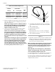
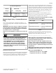
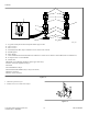
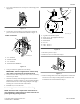
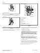
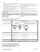
Table Of Contents
- Table of Contents
- Dimensions
- Installation
- Before You Start
- Position Unit Near Installation Area
- Remove Shipping Materials
- Connect Fill Hoses
- Connect Drain Hose to Drain Receptacle
- Gas Dryers - Connect Gas Supply Pipe
- Electric Dryer Only - Connect Electrical Plug
- Connect Dryer Exhaust System
- Position and Level the Unit
- Wipe Out Inside of Washer and Dryer Drums
- Plug In the Washer and Dryer
- Check Installation
- Check Heat Source
- Installer Checklist

• Exhausting dryer in hard-to-reach locations can be done by
installing 521P3 Flexible Metal Vent Kit (available as option-
al equipment at extra cost).
• Sufficient make-up air must be supplied to replace the air ex-
hausted by the dryer. The free area of any opening for outside
air must be at least 40 in.
2
[25806 mm
2
] per unit.
• Failure to exhaust dryer properly will void warranty.
• A dryer will dissipate 60 Btu/ft
2
[681,392 J/m
2
] of surface
area exposed to the conditioned air.
NOTE: Venting materials are not supplied with the dry-
er (obtain locally).
IMPORTANT: DO NOT block the airflow at the bottom of
the dryer’s front panel with laundry, rugs, etc. Blockage
will decrease airflow through the dryer, thus reducing
the efficiency of the dryer.
Exhaust Direction
The dryer can be exhausted to the outdoors through the back, left,
right or bottom of the dryer. EXCEPTION: Gas dryers cannot be
vented out the left side because of the burner housing.
Dryer is shipped from factory ready for rear exhaust.
Exhausting the dryer through sides or bottom can be accomplish-
ed by installing a Directional Exhaust Kit, 528P3, available as
optional equipment at extra cost.
Exhaust System
For best drying results, recommended maximum length of ex-
haust system is shown in Table 4 .
To prevent backdraft when dryer is not in operation, outer end of
exhaust pipe must have a weather hood with hinged dampers (ob-
tain locally).
NOTE: Weather hood should be installed at least 12 in-
ches [305 mm] above the ground. Larger clearances
may be necessary for installations where heavy snow-
fall can occur.
Number of 90° Elbows
Weather Hood Type
Recommended Use Only for Short Run Installations
D673I_SVG
1
1
1. 4 in. [102 mm]
D802I_SVG
1
1. 2.5 in. [64 mm]
Maximum length of 4 in. [102 mm] diameter rigid metal duct.
0 65 feet [19.8 m] 55 feet [16.8 m]
1 55 feet [16.8 m] 47 feet [14.3 m]
2 47 feet [14.3 m] 41 feet [12.5 m]
3 36 feet [11.0 m] 30 feet [9.1 m]
4 28 feet [8.5 m] 22 feet [6.7 m]
Table 4
NOTE: Deduct 6 feet [1.8 m] for each additional elbow.
NOTE: The maximum length of a 4 in. [102 mm] diame-
ter flexible metal duct must not exceed 7.87 ft. [2.4 m],
as required to meet UL2158, clause 7.3.2.A.
Installation
©
Copyright, Alliance Laundry Systems LLC -
DO NOT COPY or TRANSMIT
20 Part No. 805504R1