
Installation Instructions

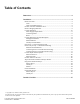
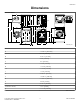
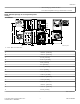
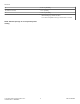
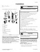
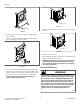
Table Of Contents
- Table of Contents
- Dimensions
- Installation
- Before You Start
- Position Unit Near Installation Area
- Remove Shipping Materials
- Connect Fill Hoses
- Connect Drain Hose to Drain Receptacle
- Gas Dryers - Connect Gas Supply Pipe
- Electric Dryer Only - Connect Electrical Plug
- Connect Dryer Exhaust System
- Position and Level the Unit
- Wipe Out Inside of Washer and Dryer Drums
- Plug In the Washer and Dryer
- Check Installation
- Check Heat Source
- Installer Checklist

Installation
Before You Start
Tools
For most installations, the basic tools you will need are:
SWD1021N_SVG
11
10
9
8
4
3
2
1
6
7
5
1. Wrench
2. 1/4 inch Driver
3. Screwdriver
4. Level
5. Wood Block
6. Pliers
7. 5/16 Inch Socket Wrench
8. Gloves
9. Teflon Tape (Gas Models)
10. Duct Tape
11. Safety Glasses
Figure 1
NOTE: If the unit is delivered on a cold day (below
freezing), or is stored in an unheated room or area dur-
ing the cold months, do not attempt to operate it until
the unit has had a chance to warm up.
NOTE: Some moisture in the wash drum is normal. Wa-
ter is used during testing at the manufacturer.
NOTE: This appliance is suitable for use in countries
having a warm, damp climate.
WARNING
Any disassembly requiring the use of tools must be
performed by a suitably qualified service person.
W299
Order of Installation Steps
The proper order of steps must be followed to ensure correct in-
stallation. Refer to the list below when installing your unit.
1. Position unit near area of installation.
2. Remove the shipping materials.
3. Connect the fill hoses.
4. Connect the drain hose to the drain receptacle.
5. For gas models only, connect the gas supply pipe. Check for
gas leaks.
6. For electric models only, connect the electrical cord.
7. Connect dryer to exhaust system.
8. Position and level the unit.
9. Wipe out inside of washer and dryer drums.
10. Plug in the washer and dryer.
11. Check installation.
12. Start and run the dryer in a heat setting to verify dryer is heat-
ing.
Position Unit Near Installation Area
Move unit so that it is within 4 feet [1.2 meters] of the desired
area of installation.
CAUTION
Washer and dryer are not designed to be operated as
separated, side-by-side units.
W187
NOTE: For best performance and to minimize vibration
or movement, install washer on a solid, sturdy and lev-
el floor. Some floors may need to be reinforced, espe-
cially on a second floor or over a basement. Do not in-
stall the washer on carpeting, soft tile or other weakly
supported structures.
Remove Shipping Materials
1. Remove two screws at bottom of front access panel. Rotate
bottom of panel out and remove panel.
Installation
©
Copyright, Alliance Laundry Systems LLC -
DO NOT COPY or TRANSMIT
9 Part No. 805504R1