Installation Instructions for Topload Washers Original Instructions Keep These Instructions for Future Reference. (If this machine changes ownership, this manual must accompany machine.) www.alliancelaundry.com Part No.
Table of Contents Dimensions and Specifications ............................................................... 4 Installation............................................................................................. 5 Before You Start.............................................................................................5 Supplies..................................................................................................... 5 Order of Installation Steps........................................
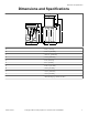
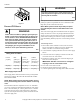
Dimensions and Specifications Dimensions and Specifications A B C D H G I J F E TLW2162N_SVG A 28 in. [711 mm] B 22.13 in. [562 mm] C *40.77 in. [1036 mm] D *53 in. [1346 mm] E 26 in. [660 mm] F 0.4 in. [10 mm] G 25.63 in. [651 mm] H *29 in. [737 mm] I *43 in. [1092 mm] J *36 in. [914 mm] *With leveling legs turned into base. Part No.
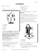
Installation Installation Before You Start Supplies For most installations, the basic supplies you will need are: 5. 6. 7. 8. 9. Position and level the washer. Plug in the washer. Add water to the washer. Check the lid switch. Check installation. 2 1 3 4 5 6 Remove the Shipping Brace and Shipping Plug 1. Remove the shipping brace from under the lid. 2. The shipping plug will be released from the base of the washer when removing the cardboard base from the washer. Refer to Figure 2 .
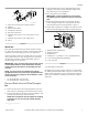
Installation WARNING To prevent personal injury, avoid contact with inlet water temperatures higher than 125° Fahrenheit [51° Celsius] and hot surfaces. W748 Water pressure must be a minimum of 20 to a maximum of 120 pounds per square inch [minimum of 138 to a maximum of 827 kPa] static pressure measured at the faucet. TLW2009N_SVG Figure 3 Connect Fill Hoses NOTE: Water pressure under 20 pounds per square inch [138 kPa] will cause an extended fill time in the washer.
Installation 4 COLD HOT 1 3 2 8 5 7 6 TLW1988N_SVG 1. 2. 3. 4. 5. 6. Filter Screen (Screen must be facing outward) Fill Hose Rubber Washer (Plain) Cold Water Connection Hot Water Connection Install this end of hose to valve connections at rear of washer. 7. Install this end of hose to water supply faucet. 8. Faucet 1. Check standpipe height. The recommended height for the standpipe is 36 inches [914 mm]. Standpipes higher than 4 feet [1220 mm] are not recommended. 2.
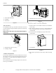
Installation 1 3 1 2 TLW2221N_SVG TLW2222N_SVG 1. 562P3 Siphon Break Kit 2. Standpipe 3. Drain Hose 1. Beaded Strap (tape if necessary) Figure 8 Figure 6 Position and Level the Washer Wall Installation For installations of this type, the drain hose MUST be secured to one of the fill hoses using the beaded strap from accessories bag. Refer to Figure 7 . NOTE: End of drain hose must not be below height of cabinet top. 1. Position washer so it has sufficient clearance for installation and servicing.
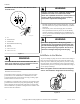
Installation WARNING 1 To reduce the risk of fire, electric shock, serious injury or death, all wiring and protective earth/ground connections MUST conform with the latest edition of the National Electrical Code, ANSI/NFPA No. 70, and such local regulations as might apply. It is the customer’s responsibility to have the wiring, fuses and circuit breakers installed by a qualified electrician to make sure adequate electrical power is available to the washer. 5 2 3 4 1. 2. 3. 4. 5.
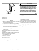
Installation Standard 120 Volt, 60 Hertz 3-Wire Effective Earth/ Ground Circuit 2 WARNING Improper connection of the equipment earth/ground conductor can result in a risk of electric shock. Check with a qualified electrician or service person if you are in doubt as to whether the unit is properly connected to a protective earth/ground. 3 1 8 6 W893 7 • 4 5 • DRY2022N_SVG 1. 2. 3. 4. 5. 6. 7. 8. L1 Earth/Ground Neutral Side Round Earth/Ground Prong Neutral 0 V.A.C. 120 ± 12 V.A.C. 120 ± 12 V.A.
Installation Check Lid Switch Washer should stop filling, agitating, and spinning when lid is opened. W376I_SVG Figure 13 Check Installation 1. Refer to Installer Checklist on the back cover of this manual and make sure that washer is installed correctly. 2. Run washer through one complete cycle to make sure it is operating properly. Part No.
Installer Checklist Installer Checklist Fast Track for Installing the Washer 1 Remove the Shipping Brace and Shipping Plug. 5 CHECK Position and Level the Washer. CHECK TLW2201N_SVG TLW1975N_SVG1 2 Wipe Out Inside of Washtub. 6 CHECK Plug In the Washer. CHECK TLW2009N_SVG D254I_SVG 3 Connect Fill Hoses. 7 COLD Add Water to the Washer. HOT CHECK CHECK TLW1988N_SVG W391I_SVG 4 Connect Drain Hose to Drain Receptacle. 8 CHECK Check Lid Switch.