Electric and Gas Models Installation/Operation Clothes Dryer Original Instructions Keep These Instructions for Future Reference. CAUTION: Read the instructions before using the machine. (If this machine changes ownership, this manual must accompany machine.) DRY722C_SVG www.alliancelaundry.com Part No.
WARNING IMPORTANT: Purchaser must consult the local gas supplier for suggested instructions to be followed if the dryer user smells gas. The gas utility instructions plus the SAFETY and WARNING note directly above must be posted in a prominent location near the dryer for customer use. WARNING Risk of fire. Highly flammable material. WARNING W881 Read all instructions before using unit.
The following information applies to the state of Massachusetts, USA. • • • • This appliance can only be installed by a Massachusetts licensed plumber or gas fitter. This appliance must be installed with a 36 inch [910 mm] long flexible gas connector. A “T-Handle” type gas shut-off valve must be installed in the gas supply line to this appliance. This appliance must not be installed in a bedroom or bathroom. © Copyright, Alliance Laundry Systems LLC - DO NOT COPY or TRANSMIT 4 Part No.
Table of Contents ...............................................................................................................3 Safety Information..................................................................................7 Explanation of Safety Messages....................................................................... 7 Important Safety Instructions........................................................................... 7 Dimensions.........................................................
Operation............................................................................................. 39 Operation Instructions for Nonmetered and Coin Slide Dryers.......................... 39 Clean Lint Filter........................................................................................ 39 Load Laundry........................................................................................... 39 Close Loading Door...................................................................................
Safety Information Safety Information Explanation of Safety Messages • Precautionary statements (“DANGER,” “WARNING,” and “CAUTION”), followed by specific instructions, are found in this manual and on machine decals. These precautions are intended for the personal safety of the operator, user, servicer, and those maintaining the machine. • DANGER • Indicates an imminently hazardous situation that, if not avoided, will cause severe personal injury or death.
Safety Information • • • • • • • • • DO NOT operate the dryer if it is smoking, grinding or has missing or broken parts or removed guards and/or panels. DO NOT tamper with the controls or bypass any safety devices. DO NOT operate individual units if they have been separated from a stack unit. Dryer will not operate with the loading door open. DO NOT bypass the door safety switch by permitting the dryer to operate with the door open. The dryer will stop tumbling when the door is opened.
Dimensions Dimensions Electric Dryers A K E B G F M H C D J I L DRY2672N_SVG A 23.5 in. [597 mm] B 8.375 in. [213 mm] C 28 in. [711 mm] D 0.4 in. [11 mm] E 8 in. [203 mm] F 46.62 in. [1184 mm] G *78.17 in. [1986 mm] H *4 in. [102 mm] I *4.5 in. [114 mm] J 26.875 in. [683 mm] K 15.4 in. [391 mm] L *15.44 in. [392 mm] M *39.13 in. [994 mm] NOTE: Exhaust openings are 4 inch [102 mm] metal ducting.
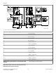
Dimensions Gas Dryers A L E B G M F P H N K C D I J O 1 DRY2673N_SVG 1. 3/8 in. N.P.T. Gas Connection A 23.5 in. [597 mm] B 8.375 in. [213 mm] C 28 in. [711 mm] D 0.4 in. [11 mm] E 8 in. [203 mm] F 46.62 in. [1184 mm] G *78.17 in. [1986 mm] H *4 in. [102 mm] I *4.5 in. [114 mm] J 26.875 in. [683 mm] K 2.3 in. [60 mm] L 15.4 in. [391 mm] M *44.87 in. [1140 mm] N *2.8 in. [70 mm] O *15.44 in. [392 mm] P *39.13 in.
Dimensions IMPORTANT: The dryer should have sufficient clearance around it for needed ventilation and for the ease of installation and servicing. For maximum drying performance, we recommend that more clearance be allowed around the dryer than the clearances that are listed throughout this manual. © Copyright, Alliance Laundry Systems LLC - DO NOT COPY or TRANSMIT 11 Part No.
Installation Installation Before You Start A Torx bit, part number 282P4, is available (as optional equipment at extra cost) for installing the Torx security screws. Supplies A Torx bit holder, part number 24161, is available (as optional equipment at extra cost) to be used with the Torx bit. For most installations, the basic supplies you will need are: 1 2 3 Position and Level the Dryer 4 1. Install the four rubber feet (in accessories bag). 2. Select a location with a solid floor.
Installation Front View A A DRY2667N_SVG Side View B D C E E 1 DRY2668N_SVG 1. Outer Wall of Enclosure Figure 3 Area Description Free Standing/Alcove Installation A Dryer sides 0 in. [0 mm] B Dryer top (rear 24 in. [610 mm]) 12 in. [305 mm] Table 1 continues... © Copyright, Alliance Laundry Systems LLC - DO NOT COPY or TRANSMIT 13 Part No.
Installation Area Description Free Standing/Alcove Installation C* Dryer rear 4 in. [102 mm] D Dryer Top (front 4 in. [201 mm]) 0.5 in. [13 mm] E Exhaust duct clearance to combustible ma- 2 in. [51 mm] terial * Rear clearance is minimum. 6 inches [152 mm] is recommended when venting through rear of unit. Table 1 NOTE: For new installations, it is suggested to locate top of wall vent 42 inches (106.7 cm) above floor to make venting easier to connect.
Installation IMPORTANT: Installing in-line filters or lint collectors will cause increased static pressure. Failure to maintain the secondary lint system will decrease dryer efficiency and will void machine warranty. • • • • 1 2 DRY2540N_SVG 1. Correct 2. Incorrect Figure 4 • • • • • • • • • • • • • • • DO NOT use plastic, thin foil or type B ducting. Rigid metal duct is recommended. Locate dryer so exhaust duct is as short as possible.
Installation Weather Hood Type Number of 90° Elbows Recommended Use Only for Short Run Installations 1 1 D673I_SVG 1. 4 in. [102 mm] 1 D802I_SVG 1. 2.5 in. [64 mm] Maximum length of 4 in. [102 mm] diameter rigid metal duct. 0 65 feet [19.8 m] 55 feet [16.8 m] 1 55 feet [16.8 m] 47 feet [14.3 m] 2 47 feet [14.3 m] 41 feet [12.5 m] 3 36 feet [11.0 m] 30 feet [9.1 m] 4 28 feet [8.5 m] 22 feet [6.7 m] Table 2 NOTE: Deduct 6 feet [1.8 m] for each additional elbow.
Installation 1 2 4 3 DRY2674N_SVG 1. 2. 3. 4. 58786 Backdraft Damper (Available through your local authorized parts source) Clean Out Cover (Must be provided). Inspect monthly. Weather Hood or Sweep Elbow (No cap or screen) 24 in. [610 mm] Minimum Clearance to Roof/Ground Figure 5 © Copyright, Alliance Laundry Systems LLC - DO NOT COPY or TRANSMIT 17 Part No.
Installation Horizontal Exhaust Installation: Exhaust Air Flow Maximum Length of Duct 30 feet [9.1 m] 1 2 9 A B C D E F G H I J K 3 7 4 8 6 5 D686I_SVG 1. 2. 3. 4. 5. 6. 7. 8. 9. Where the exhaust duct pierces a combustible wall or ceiling, the opening must be sized per local codes. Wall 2 in. [50 mm] Minimum or Clearance per Local Codes No Screen or Cap 24 in.
Installation Vertical Exhaust Installation WARNING 3 4 To reduce the risk of gas leaks, fire or explosion: 2 • 1 • • 7 • 5 6 D753I_SVG Roof 24 in. [610 mm] Minimum Clearance to Roof/Ground No Screen or Cap Wall 2 in. [50 mm] Minimum Where the exhaust duct pierces a combustible wall or ceiling, an opening must be sized as shown or per local codes. 7. Connect to Dryer • 1. 2. 3. 4. 5. 6. • W315 1. Make certain your dryer is equipped for use with the type of gas in your laundry room.
Installation Natural Gas Altitude Adjustments Altitude 1 Orifice Size feet [m] inches [mm] # 5 Part Number 3,000 [915] 42 0.0935 [2.37] D503777 5,500 [1,680] 43 0.0890 [2.26] D503778 7,000 [2,135] 44 0.0860 [2.18] 58719 9,000 [2,745] 45 0.0820 [2.08] D503779 10,500 [3,200] 46 0.0810 [2.06] D503780 2 D233I_SVG 1. New Stainless Steel Flexible Connector – (Use design CSA certified connector) Use only if allowed by local codes 2. 1/8 in. NPT Pipe Plug 3.
Installation WARNING L.P. Altitude Adjustments Altitude Improper connection of the equipment earth/ground conductor can result in a risk of electric shock. Check with a qualified electrician or service person if you are in doubt as to whether the dryer is properly connected to a protective earth/ground. Orifice Size feet [m] inches [mm] No. Part No. 3500 [1070] 54 0.0550 [1.40] D503785 7500 [2290] 55 0.0520 [1.32] 58755 11000 [3355] 56 0.0465 [1.
Installation Three-Wire Three-Wire Connection 1 2 1 2 3 8 3 4 7 4 D275I_SVG Four-Wire 5 2 6 3 1 D679I_SVG 1. 2. 3. 4. 5. 6. 7. 8. 4 D006I_SVG 1. 2. 3. 4. Typical Receptacle Power Cord Stain Relief Nut Strain Relief Figure 10 Figure 9 © Copyright, Alliance Laundry Systems LLC - DO NOT COPY or TRANSMIT Ground Wire Ground to Neutral Wire Neutral Terminal “L2” Terminal Center Wire (Neutral) Strain Relief (Not supplied with dryer) Ground Screw “L1” Terminal 22 Part No.
Installation NOTE: Dryer is shown with access cover removed for illustration purposes only. NEVER operate the dryer with access cover removed. Four-Wire Connection 1 Connecting Power Cord with Three-Wire Plug 4 3 2 5 1 6 7 8 9 1. 2. 3. 4. 5. 6. 7. 8. 9.
Installation 6 7 8 1 9 14 4 10 5 11 2 2 12 13 3 16 L1 L2 15 L1 L2 D816I_SVG 1. A typical 30-Amp Three-Wire Receptacle NEMA Type 10-30R 2. 120 ± 12 V.A.C. 3. 240 ± 12 V.A.C. 4. Intermediate Fuse Box (may be omitted if service entrance box is fused) 5. Wall Receptacle 6. Power Supply 7. 3-Wire Earth/Ground Neutral 120/240 Volt, 60 Hertz AC 1 Phase Service Entrance Switch Box (Refer to NOTE above) 8. 30 Ampere Fuses or Circuit Breaker 9. Neutral Wire 10.
Installation 3. Use a strain relief and insert end of power cord through power supply hole. 2 1 3 4 7 7 6 Figure 14 7 5 7 D696I_SVG 4. Use the three screws from the accessories bag to attach the power cord wires to the terminal block. Refer to Figure 15 . DRY2016N_SVG 3-Wire Connection 1. 2. 3. 4. 5. 6. 7. 1 2 Typical Four-Wire Receptacle Power Cord – Not Supplied with Dryer Strain Relief Nut Strain Relief 0 V.A.C. 240 ± 12 V.A.C. 120 ± 12 V.A.C. Figure 16 4 3 1.
Installation 4-Wire Connection 8 1 7 1 2 DRY2468N_SVG 1. Earth/Ground Screw 3 6 Figure 18 DRY2482N_SVG 1. 2. 3. 4. 5. 6. 7. 8. DRY2469N_SVG 1. Strain Relief Figure 19 5. Attach power cord earth/ground (green) wire to rear bulkhead using earth/ground screw removed in Step 3. 4 5 4. Use a strain relief and insert end of power cord through power supply hole. Neutral Terminal “L2” Terminal Black White Earth/Ground Red “L1” Terminal Earth/Ground to Neutral Wire Figure 20 6.
Installation The door on this dryer is completely reversible. To reverse door proceed as follows: 1. Remove four hinge attaching screws. D273P_SVG Figure 24 D675I_SVG 5. Remove door strike from door liner and reinstall on opposite side. Figure 21 2. Remove all nine screws. DRY1917N_SVG Figure 25 D272P_SVG 6. Insert liner under flange on bottom of door, then push top of door liner into place. Figure 22 3. Pull bottom of door liner out, then pull down, removing door liner from door panel.
Installation 8. Using screwdriver, remove two door plugs, and reinstall on opposite side of door opening. D317S_SVG Figure 28 9. Reinstall four hinge attaching screws, removed in Step 1. Figure 30 Plug In the Dryer D606I_SVG Figure 29 Wipe Out Inside of Dryer Before using dryer for the first time, use an all-purpose cleaner, or a detergent and water solution, and a damp cloth to remove shipping dust from inside dryer drum.
Installation Plug Cord Into Separately Fused 15 Amp Circuit WARNING To reduce the risk of fire, electric shock, serious injury or death, all wiring and grounding MUST conform with the latest edition of the National Electrical Code, ANSI/NFPA 70, or the Canadian Electrical Code, CSA C22.1, and such local regulations as might apply. It is the customer’s responsibility to have the wiring and fuses installed by a qualified electrician to make sure adequate electrical power is available to the dryer.
Installation 2. Close the loading door and start the dryer in a heat setting (refer to the operation instructions). The dryer will start, the igniter will glow red and the main burner will ignite. WARNING This unit is equipped with a three-prong (earth/ ground) plug for your protection against shock hazard and should be plugged directly into a protective earth/ ground three-prong receptacle. Do not cut or remove the earth/ground prong from this plug.
Installation 1. Air Shutter Lockscrew 2. Air Shutter 3. 1/8 in. [3.1 mm] Pipe Plug (For checking manifold pressure) Figure 33 © Copyright, Alliance Laundry Systems LLC - DO NOT COPY or TRANSMIT 31 Part No.
Vending Vending Coin Slide Guards Using sheet metal screws from accessories bag (located in lower cylinder), install coin slide guards (located in accessories bag in lower cylinder) to front of dryer’s control cabinet. Refer to Figure 34 . In Door Open Mode, the control turns off the heater and motor when the door is opened during a run cycle. The timer will continue to count down time and the IN USE LED is lit. End of Cycle Mode In End of Cycle Mode, a cycle is complete and the IN USE LED is off.
Vending NOTE: The control reads the dipswitch settings at power-up. The control must be powered down to change the dipswitch settings. NOTE: The control must be powered down for 10 seconds before the dipswitch can be changed. Dipswitch1 Bank Refer to Table 7 .
Vending Dipswitch Settings Heat Switch Number Heat Time Per Coin Pulse (in minutes) 1 2 3 4 5 6 1 OFF OFF OFF OFF OFF OFF 2 ON OFF OFF OFF OFF OFF 3 OFF ON OFF OFF OFF OFF 4 ON ON OFF OFF OFF OFF 5 OFF OFF ON OFF OFF OFF 6 ON OFF ON OFF OFF OFF 7 OFF ON ON OFF OFF OFF 8 ON ON ON OFF OFF OFF 9 OFF OFF OFF ON OFF OFF 10 ON OFF OFF ON OFF OFF 11 OFF ON OFF ON OFF OFF 12 ON ON OFF ON OFF OFF 13 OFF OFF ON ON OFF OF
Vending Heat Switch Number Heat Time Per Coin Pulse (in minutes) 1 2 3 4 5 6 29 OFF OFF ON ON ON OFF 30 ON OFF ON ON ON OFF 31 OFF ON ON ON ON OFF 32 ON ON ON ON ON OFF 33 OFF OFF OFF OFF OFF ON 34 ON OFF OFF OFF OFF ON 35 OFF ON OFF OFF OFF ON 36 ON ON OFF OFF OFF ON 37 OFF OFF ON OFF OFF ON 38 ON OFF ON OFF OFF ON 39 OFF ON ON OFF OFF ON 40 ON ON ON OFF OFF ON 41 OFF OFF OFF ON OFF ON 42 (preset at fac- ON t
Vending Heat Switch Number Heat Time Per Coin Pulse (in minutes) 1 2 3 4 5 6 57 OFF OFF OFF ON ON ON 58 ON OFF OFF ON ON ON 59 OFF ON OFF ON ON ON 60 ON ON OFF ON ON ON 61 OFF OFF ON ON ON ON 62 ON OFF ON ON ON ON 63 OFF ON ON ON ON ON 64 ON ON ON ON ON ON Table 9 Test Setting When testing coin slide operation or other troubleshooting, set dipswitch with this shorter cycle: 1. Unplug the machine power cord. 2.
Vending 6. Install coin slide extension assembly onto top of coin slide using two remaining screws and lockwashers. Place lockwasher under head of screws, above bracket “A”. Refer to Figure 38 . 2 3 1 2 1 4 7 5 6 1. 2. 3. 4. 5. 6. 7. TLW1610K_SVG Shoulder Bolt Spring Flat Washer Rounded Corner Nut Extension Lever Extension Bracket TLW2164N_SVG 1. Coin Slide Extension Assembly 2. Spring Installed Figure 38 7.
Vending NOTE: To avoid long run-down time (45 minutes factory default) when testing operation, refer to Test Setting section. Installing Coin Slide Assembly Into Meter Case: Option Two 1. Install coin slide according to manufacturer’s instructions. 2. Insert coins into coin slide and slowly push slide in. Stop before coins fall into coin box. This will allow installing extension through meter case service door opening. 3. Install slide extension onto top of coin slide using two screws.
Operation Operation Operation Instructions for Nonmetered and Coin Slide Dryers WARNING To reduce the risk of fire, electric shock, or injury to persons, read the IMPORTANT SAFETY INSTRUCTIONS before operating this appliance. W727 IMPORTANT: Remove all objects from pockets such as lighters and matches. D717I_SVG Figure 41 Close Loading Door 1. Close loading door. 2. Dryer will not operate with the door open. This appliance shall not be used to dry off solvents or dry cleaning fluids.
Operation 3. Remove knits when slightly damp because overdyring may cause shrinkage. Do not tumble dry knit woolens. Should dryer stop before cycle is completed, the motor overload protector may have cycled. Refer to Maintenance section. NOTE: This machine includes an extended tumble feature. Starting 20 minutes after a cycle ends, the cylinder will tumble for two minutes every hour without heat, up to 18 hours or until door is opened.
Operation IMPORTANT: To avoid damage to dryer, do not use more than one fabric softener sheet per load. HIGH TEMP LOW TEMP MED TEMP DELICATES START D717I_SVG Figure 48 DRY2688N_SVG Close Loading Door Figure 51 1. Close loading door. 2. Dryer will not operate with the door open. Insert Coins or Card To Insert Coins 1. Insert coin(s) in coin slot. 2. Check pricing as seen on digital display.
Operation WARNING To prevent the risk of fire, never stop a dryer before the end of the drying cycle unless all items are quickly removed and spread out so that the heat is dissipated. W756 Indicator Lights START START is lit whenever the dryer is not in a cycle, the full vend price has been satisfied and the dryer door is closed. When the START pad is pressed, the cycle will begin or resume.
Maintenance Maintenance Lubrication WARNING All moving parts are sealed in a permanent supply of lubricant or are equipped with oilless bearings. Additional lubrication will not be necessary. Any disassembly requiring the use of tools must be performed by a suitably qualified service person. Care of Your Dryer W299 WARNING To reduce the risk of an electric shock, serious injury or death, disconnect the electrical service to the dryer before cleaning the interior.
Maintenance Motor Overload Protector The dryer’s motor overload protector stops the motor automatically in the event of an overload. After cooling, the overload protector will reset itself. Dryer can be restarted by pressing the START pad. If overload protector cycles again, remove the dryer from use and call the service person to correct the problem. For Energy Conservation • • • • • • • • • • Make sure the lint filter is always clean. Do not overload dryer. Do not overdry clothes.
Troubleshooting Troubleshooting Try these troubleshooting tips before making a service call. They may save you time and money. Dryer Symptom Dryer won’t start Possible Cause/Solution • • • • • • • Dryer won’t heat • • • • • • Dryer doesn’t dry clothes satisfactorily • • • • • Dryer is noisy • • • Insert coin(s) or card, if required. For dryers equipped with a power cord, make sure the power cord is plugged all the way into the electrical outlet. Make sure loading door is closed. Press START pad.
Troubleshooting Dryer Symptom Possible Cause/Solution Clothes are too wrinkled • • Check heat setting. Overdrying can cause wrinkling. Check load size. Large loads may not tumble properly and may cause wrinkling. Clothes have odor • Check room for odors before drying clothes. Any odor (fried foods, paint, varnish, cleaners, burning wood, etc.) will transfer to clothing as the dryer draws air from the room. Ventilate room before drying clothes.
Contact Information Contact Information If service is required, contact the nearest Factory Authorized Service Center. Model Number If you are unable to locate an authorized service center or are unsatisfied with the service performed on your unit, contact: Alliance Laundry Systems Shepard Street P.O. Box 990 Ripon, WI 54971-0990 U.S.A. www.alliancelaundry.com Phone: +1 (920) 748-3121 Serial Number Please include a copy of your bill of sale and any service receipts you have.
Installer Checklist Installer Checklist Fast Track for Installing the Dryer 1 Position and Level the Dryer. 6 CHECK Wipe Out Inside of Dryer. CHECK DRY2634N_SVG 2 Connect Dryer Exhaust System. 7 CHECK Plug In the Dryer. Electric CHECK DRY2540N_SVG1 D275I_SVG1 Gas TLW2289N_SVG 3 8 GAS ONLY • • Recheck Steps. Connect Gas Supply Pipe. Check for Gas Leaks. D233I_SVG1 CHECK 4 CHECK ELECTRIC ONLY • 9 Connect Electrical Cord.