
Owner's manual


2-1/16" and 2-5/8" Tachometer Instructions
+12 volts keyed ignition
(Red)
(Black)
Ground
(White)
+12 volts Dash lighting
Power distribution cable to plug all gauges into
(dial lighting wire)
(Pointer lighting wire)
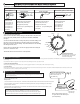
Mount Tachometer in good location for easy viewing. Use included spin ring (or pedestal mount bracket) to secure the gauge.
Hook up the red, black and white wires. (Refer to the schematic above.)
Your vehicle ignition system will fall under one of these 4 ignition types. The type of ignition system will determine where the yellow wire is
connected and what the number of pulses per revolution the tachometer should be set to.
Type #1 (single coil) - Up until the 1990’s tachometers picked up the signal from the (-) side on a single ignition coil, reading every pulse sent
to all the cylinders. For example, an 8 cylinder (4 stroke) engine fires 4 spark plugs per revolution or all 8 spark plugs in 2 revolutions.
Connecting the tachometer yellow signal wire to the negative side of the single coil on an 8 cylinder results in pickingup 4 sparks in 1 revolution
(see fig 1). This type of ignition was used pre-dominantly until the 1990’s and distributes sparks to each spark plug. In some vehicles during
the 90’s the coil and distributer merged into one unit, but it is the same ignition system - one coil that distributes sparks to all cylinders. When
connecting the yellow wire to this style of ignition you will be picking up all cylinder sparks (see fig 5).
Type #2 (coil pack) - (fig 2) is a 96 Mustang V8 with twin coil packs. Coil pack #1 (C1) controls the firing of 4 spark plugs and coil pack #2 (C2)
controls the remaining 4 spark plugs. 2 or more separate coils are within each coil pack assembly. In this example each of the 2 coils within each
coil pack sends sparks to 2 cylinders at the same time. When one cylinder is firing in the compression stroke, it’s paired cylinder is “waste” firing in
the exhaust stroke. Each separate coil within the pack is controlled by it’s own trigger wire. In other words, if you hooked up the yellow wire to one
coil trigger wire within one coil pack, it will see only a fraction of the total engine sparks (see fig 5).
Type #3 (coil on plug) – An individual coil is placed directly on top of each spark plug eliminating the spark plug wires. The yellow wire, when
hooked up to any coil, will pick up only 1 pulse per 2 revolutions or 1/2 pulse per 1 revolution (see fig 3). For this type of ignition the yellow wire
from the tachometer will connect to the trigger wire on one of the coils. Typically there will be 3 or 4 colored wires coming off of each coil. The
trigger wire will be the wire that changes color from one coil to the next. For example, all coils may have red, gray and black wires coming off of
them, but the fourth wire will be blue on one coil and green on the next coil.
Type #4 (tach output from ECU) Some vehicles will have a tachometer output wire coming from the ECU. The yellow wire from our tachometer
can receive signal from the ECU by following the diagram in fig 4. 4.7k Ω resistor and shrink tubing are included with gauge.
In summary, figure out how many cylinders you are picking up with the yellow wire and set the respective number of pulses per revolution
(see step 4). The tachometer can be configured to work on .5 pulse (coil on plug) up to 6 pulses per revolution. Use Fig 5 as a starting point
when hooking up the yellow wire.
- negative
+
Y
e
l
l
o
w
w
i
r
e
1 revolution of engine
8 CYL early style single coil example
(fig 1)
1 revolution of engine
8 CYL twin coil packs
(fig 2)
C2
To spark plugs
Y
e
l
l
o
w
w
i
r
e
C1
2 revolutions of engine
8 CYL coil on plug
(fig 3)
Y
e
l
l
o
w
w
i
r
e
Setup the Tachometer to run
2 pulses per rev when
connecting it to the engines’ ECU.
ECU
Tachometer (Yellow)
ACC (12v)
4.7K -10K Ω 0.25 watt minimum
(fig 4)
(fig 5: see page 2)
Caution:
1 Do NOT handle coil wires when car is running.
High voltage is sometimes present.
2. Do NOT try to splice directly into a spark plug
wire. This will damage tachometer.
1
2
Ground (black)
+12 volts Dash lighting (white)
(Yellow)
snap connector
negative
coil /tach output
Note: Tie both lighting white wires together
and both black ground wires together.
INVERTER IS REQUIRED FOR GAUGE DIAL LIGHTING
(Main gauge power)
INVERTER
Power Draw = 0.2 Amp
5 Amp Inline Fuse Recommended
for +12 Keyed Ignition
WARRANTY - Speedhut inc. warrants to the consumer for a period of 5 years from the date of purchase that the product will be free from defects in materials or workmanship.
Speedhut warrants to the consumer for a "LIFE-TIME" that the product circuit board will be free from defects in materials or workmanship.
Please contact Speedhut service department If you have a problem with this gauge.
Speedhut Inc. 165 North 1330 West B2, Orem, Utah 84057 | support@speedhut.com | (801) 221-1460 (9am - 5pm MST)
Inverter/Black Box Note: E18-686-5CR is single gauge inverter to light single gauge.
C01-18N-2 & C11-18A01 are multiple gauge lighting inverters that can light up to 8 gauges.
***Protect any unused connectors. Damage to an unused connector could cause inverter failure.***
Some 2-1/16" Tachometers models will have a button on the front of the gauge, but some 2-1/16" tachometers and all 2-5/8" Tachometers will come with an 18” cable
with a button on it that will plug into the back of the gauge (left side facing front of the gauge). This button is for setting PPR (step 4) and displaying peak recall (step 5).
Model Variation
wiring is identical
3. Wear safety glasses.