
Instructions / Assembly

4 www.eccomfg.com ECCO Manufacturing™
Rev. 1
4) Pipe Assembly
Sections of ECCO B-Vent round pipe are joined together in the
following ways:
• Sizes 3", 4", 5" – Align the seams, slide the upper vent over
the lower vent and rotate the upper vent 1/4 turn to the left.
• Sizes 6", 7", 8" – Align the seams, slide the upper vent over
the lower vent and snap the lock into place.
• Correctly assembled pipes will have the bottom end of the
vent meeting the step of the adjoining vent. Make sure
locking tabs are securely locked behind locking edge. If not,
take a screwdriver and push tabs into place.
• The portion of the vent which may extend through
accessible spaces shall be enclosed (allowing minimum
1" clearance to combustibles) to avoid personal contact with
the vent and damage to it.
• Should the vent pipes require dismantling, simply locate a
punch mark on the bottom vent and rotate the top vent to
the right until the locking tabs snap over the stops. The vent
can then be pulled apart.
5) Fire Stop Spacers
Fire stop spacers are required below and above each floor and
ceiling level penetrated by the vent. Nail the fire stop spacers
securely over each framed opening.
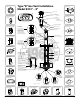
6) Connectors
Only ECCO B-Vent draft hood connectors should be used
between the appliance and the venting system. Some
appliances require Type B-Vent as a complete dedicated
system from the flue collar of the appliance to the termination
of the vent to the outside atmosphere.
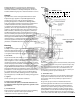
• Install Double Wall increasers with #8 × 1/4" screws provided
as shown in Figure 1.
7) Elbows
• When adjusting elbows for offset applications, grasp both
inner conduit and outer casing and the elbows will turn
freely.
• IMPORTANT: The offset must be supported with hanger
strap to prevent the weight from stressing the elbows, as
shown in Figure 1.
8) Adjustable Lengths
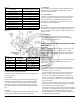
Adjustable pipe lengths can be shortened as follows (refer to
Figure 3). With sharp tin snips, carefully cut the outer liner first,
minimum length 3-1/2", followed by the inner conduit. Inspect
the outer liner/inner conduit after cutting to ensure they are
not damaged during cutting. Slide the shortened, adjustable
length over standard B-Vent pipe length with minimum
2" overlap. Secure adjustable length with (2) #8 × 1/4" screws
provided.
Figure 3
9) Tees and Wyes
• Tees and wyes are used to combine connectors from 2 or
more appliances into a common vent.
• When using aluminum tee reducers to adapt from single
wall to double wall, fasten the aluminum tee reducer to the
B-Vent using (2) #8 × 1/2" sheet metal screws. Bend tabs
at 90° and fasten single wall pipe with sheet metal screws
through holes provided in tabs.
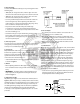
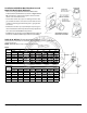
10) Terminations
Where the pipe sections pass through the roof, a hole must be
cut to provide a minimum clearance (air space) of 1" between
the pipe and construction materials. Straight lengths of
pipe are run up above the roof (see Table 1). A roof flashing
is placed down over the pipe, and adjusted so it fits tightly
against the roof, with the pipe section held in a position
maintaining the 1" minimum clearance from combustibles.
The flashing is then nailed to the roof. The roofing material
(shingles, asphalt paper, etc.) should overlap the top edge
(uphill side) of the flashing. Non-hardening sealant is placed
around the joint between the flashing and the vertical pipe
section and the storm collar is then placed over this joint, to
make a watertight seal. Add sufficient pipe sections to attain
the height specified in Table 1.
• Secure the rain cap by pushing down until snap-in head is
locked. To remove the cap, grip the skirt with both hands
and pull upwards with a rocking motion.
FLASHING
STORM
COLLAR
SEALANT
See
Table 1
RAINCAP (HIGH WIND)