
Instructions / Assembly


Chapter 28 Ductwork
battery operated drill, chisel, gloves, lineman's pliers,
diagonal cutters, and longnose pliers. NOTE:
Aviation snips are used for cutting openings in
sheet metal. Never use them to cut wire.
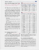
28.7 How to Lay out a Duct System —#
The heating and cooling units should be matched to
the square footage of the building's floor space. In addi-
tion, they should be able to distribute a set quantity of air
(measured in cubic feet per minute, or cfm) to the
living area through the duct system, Figure 28-19. A
living space of 1200 sq. ft. is matched up with a
100,000 Btu furnace and a 3-ton air conditioner,
Figure 28-19A. Come off the plenum with one or two
main trunk lines having a total capacity of 1200 cfm,
running toward the living areas. Figure 28-19B.
EXAMPLES:
Two 12" round duct main trunks @ 620 cfm each
= 1200 cfm
Three 10" round duct main trunks @ 400 cfm
each = 1200 cfm
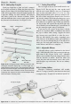
With the main trunk lines installed, begin branching
from the mains with smaller lines running to the various
rooms. Always keep a constant rate of airflow (cfm) to
the various rooms. A branch line must properly reduce
in size to maintain a constant airflow from the trunk
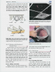
line. A vclocimeter or anemometer. Figure 28-20, is
often used to check and correct airflow problems. Such
meters can read velocity (speed), cfm (flow), and
temperature.
28.8 Installing Startinj
and Takeoffs -
Collars
Starting collars and takeoffs are installed on the
plenum to begin a "run." A starting collar is used with
round duct, while a takeoffis used with rectangular duct.
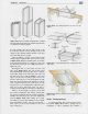
28.8.1 Starting Collars for Round Duct
It is best to mount the starting collar on the side of
the plenum, 6" below the top, to ensure proper mixing
of the air. Never install a collar on top of the plenum.
To install a starting collar, first mark the proper size
opening with a pencil or metal scribe, Figure 28-21.
Next, pierce the metal surface with a sharp tool and
use snips to cut the opening. Then, insert the collar
into the opening and fold the tabs down inside the
plenum. Finally, secure the collar with three sheet
metal screws and seal it with mastic.
Sq. Ft. of
Floor Area
400
800
1,200
1,600
2,000
Furnace
BTU's
33,000
67,000
100,000
133,000
167,000
Air Conditioner
Tonnage
1
Ton
2 Ton
3 Ton
4 Ton
5 Ton
CFM of
Air Movement
400
800
1,200
1,600
2,000
Dimensions
4" Round
5" Round
6" Round
2
1
/
4
"X 10"
2
1
/4"X12"
3
1
/4" X 10"
3V4"X 12"
7" Round
3
1
/4"X14"
8" Round
8" X 8"
9" Round
10" Round
12" X 8"
12" Round
16"X8"
14" Round
16" Round
Approx. CFM
30
60
100
60
70
100
120
150
140
200
260
290
400
440
620
660
930
1300
Sq. In.
12.57"
19.64"
28.27"
23.00"
27.00"
33.00"
39.00"
38.48"
46.00"
50.27"
64.00"
63.62"
78.54"
96.00"
113.09"
128.00"
153.93"
201.06"
B
Figure 28-19. A—Heating and cooling units
floor area. B—Approximate cfm of airflow (at
700 ft./min.) for different-size ducts.
matched to
a velocity of
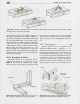
28.8.2 Takeoff for Rectangular Duct
Manufactured takeoffs arc available in many sizes,
such as 8"x 8", I2"x 8", 14"x 8", or 16"x 8", and
mount easily on any side of the plenum. It is best to
mount the takeoff 6" below the top of the plenum to
ensure proper mixing of the air, Figure 28-22. When
the furnace is located at one end of the house, the
extended plenum may run to the opposite end. When
the furnace is located at the center of the house, two
takeoffs are used to provide an extended plenum on
each side of the furnace.