INSTRUCTION MANUAL FOR SPEEDOTRON BROWN LINE EQUIPMENT
WELCOME TO SPEEDOTRON Thank you for purchasing Speedotron Brown Line equipment. The name Speedotron is synonymous with professional workmanship and the production of the finest electronic flash equipment you’ll find anywhere. Backed by years of experience, our engineers have developed the Brown Line system to economically handle tough lighting situations through a wide range of power demands. Speedotron’s business has grown over the years without much fanfare or advertising.
GENERAL POWER SUPPLY INSTRUCTIONS For maximum equipment life and for safe, dependable operation of power supplies we advise you to follow these general rules. Unpack equipment carefully. Examine all packing material. Should you notice any breakage or defect, notify the dealer and carrier (if shipped to you) immediately. Then please read all instructions before assembling your flash system in order to avoid damage to your equipment or injury to yourself.
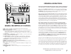
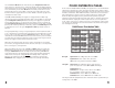
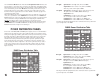
Symmetrical/Asymmetrical Ready/Push to flash button Power on LED Hi-temp LED Power Model OPERATING INSTRUCTIONS Full/Half/Quarter Operation of the D604, D1204 and D1604 power supplies is simple and straight forward. This sequence of operation is suggested for maximum life and dependability. Make sure that the Model and Power switches are in the off position and the Push to Reset button is fully depressed into its socket. Connect light head cable(s) to the Light Unit Outlet(s) on the power supply.
Turn on Power and Model switches. Wait until the green Ready/Push to Flash illuminates and press to check if the unit is operational. The light unit(s) should flash instantly when this button is pressed. If you wish to check the function of each individual light unit, we recommend that you turn off the Model switch and hold your hand in front of (not inside) the light unit to be tested. When you fire the unit you will feel the heat of the flash.
D1204 Power Distribution Table ?@@@@@@@@@@@@@@@@@@@@@@@@@@@@@@@@@@@@@@@@@@@@@@@@@@@@@@@@@@@@@@@@@@@@@@@@@@@@@@@@@@@@@@@@@@@@@@@@@@@@@@@@@@@@@@@@@@@@@@@@@@@@@@@@@@@@@@@@@@@@@@@@@@@@@@@@@@@@@@@@@@@@@@@@@@@@@@@@@@@@@@@@@@@@@@@@@@@@@@@@@@@@? ?@@@@@@@@@@@@@@@@@@@@@@@@@@@@@@@@@@@@@@@@@@@@@@@@@@@@@@@@@@@@@@@@@@@@@@@@@@@@@@@@@@@@@@@@@@@@@@@@@@@@@@@@@@@@@@@@@@@@@@@@@@@@@@@@@@@@@@@@@@@@@@@@@@@@@@@@@@@@@@@@@@@@@@@@@@@@@@@@@@@@@@@@@@@@@@@@@@@@@@@@@@@@? ?@@@@@@@@@@@@@@@@@@@@@@@@@@@@@@@@@@@@@@@@@@@@@@@@@@@@@@@@@@@@@@@@@@
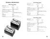
TECHNICAL SPECIFICATIONS D604 Power Supply Maximum power: . . . . . . . . . . . . . . . . . . . . .600Ws Number of light unit outlets: . . . . . . . . . . . .4 Recycle time: watt-seconds seconds (to 85% voltage, ANSI standard) . . . . . . . . . . . . .600 2.3 300 1.3 Flash duration . . . . . . . . . . . . . . . . . . . . . . . .1/590 sec. (1.7 milliseconds) (at full power w/one M11Q light unit measured 1/2 to 1/2 peak as per ANSI PH3.40) Maximum power into one light unit: . . . . . . .
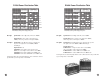
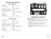
Symmetrical/Asymmetrical Power input Model Full/Half Power OPERATING INSTRUCTIONS Operation of Brown Line power supplies is simple and straight forward. It is suggested that this sequence of operation be utilized for maximum life and dependability. Make sure that the Model and Power switches are in the off position and the Push to Reset buttons are fully depressed into their sockets. Connect light head cable(s) to the Light Unit Outlet(s) on the power supply.
Turn on Power and Model switches. Wait until the Ready/Push to Flash illuminates and press the button to check if the unit is operational. The light unit(s) should flash instantly when this button is pressed. If you wish to check the function of each individual light unit, we recommend that you turn off the Model switch and hold your hand in front of (not inside) the light unit to be tested. When you fire the unit you will feel the heat of the flash.
TECHNICAL SPECIFICATIONS Light unit outlets Symmetrical/Asymmetrical Power Model D402 Power Supply Maximum power: . . . . . . . . . . . . . . . . . . . . .400Ws Number of light unit outlets: . . . . . . . . . . . .4 Recycle time: watt-seconds seconds (to 85% voltage, ANSI standard) . . . . . . . . . . . . .400 1.75 200 0.9 Flash duration : . . . . . . . . . . . . . . . . . . . . . . .1/1200 sec. (.8 milliseconds) (at full power w/one M11Q light unit measured 1/2 to 1/2 peak as per ANSI PH3.
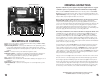
TECHNICAL SPECIFICATIONS OPERATING INSTRUCTIONS Make sure that the Model and Power switches are in the off position and the Push to Reset button is fully depressed into its socket. Connect light head cable(s) to the Light Unit Outlet(s) on the power supply. The outlets are wired in parallel so it does not matter in what sequence light head cables are connected. Never connect or disconnect light units while power is on. Do not insert or remove flash tubes while power is on.
BROWN LINE LIGHT UNITS General Instructions and Information The Speedotron Brown Line light units described here may be used with any Speedotron Brown Line power supply using the five-pin MS outlet. All light units are supplied with a 20' wired-in cable. Unpack and examine all equipment carefully. Should you notice any breakage or defect, notify your dealer (and the carrier if it was shipped to you) immediately. The flash tube(s) and model lamp(s) are packed in their original cartons.
Technical Specifications FIXED REFLECTOR LIGHT UNITS MW3R and MW3R/CC The MW3R series light units share a common base, but are differentiated by the type of flash tube each contains. They feature 5-1/2" fixed reflector and are functional as background or hair lights. When installing flash tubes and model lights be sure that the unit is disconnected from the power supply.
UNIVERSAL LIGHT UNITS (REMOVABLE REFLECTORS) M11, M11/CC, M11Q and M11Q/CC The M11 series universal light units share a common base, but are differentiated by the type of flash tube each contains. They are supplied with a removable 11-1/2" reflector when purchased individually or include a 7" umbrella reflector when purchased in an umbrella kit or flash systems. When installing flash tubes and model lamps be sure that the unit is disconnected from the power supply.
GENERAL MAINTENANCE AND CARE All Speedotron Brown Line equipment is ruggedly built. Nevertheless, it should be treated with the same care given to other pieces of quality photographic equipment. To protect the user, all Speedotron equipment is designed to be safe when used in accordance with instructions. To assure the maximum in safe, dependable service, the following guidelines should be carefully observed. • Avoid kinking or pulling cables. Disconnect cables by pulling on the plug only.
FLASH DURATION GUIDE NUMBERS Guide numbers provide a starting point in calculating the proper exposure for pictures taken with flash. A guide number is a constant numerical value (for a given film speed/ISO) determined by multiplying the light source-to-subject distance by the f-stop in use on the lens. Consequently, dividing a given (known) guide number by the light source-to-subject distance will yeld the proper f-stop.
SPEEDOTRON’S LIMITED WARRANTY Speedotron guarantees to repair or replace, free of charge, any part or parts (except for flash tubes and modeling lamps) found by factory inspection to be defective due to faulty material or workmanship, provided the equipment is returned to our factory prepaid. The period of warranty is two years from the date of original purchase.