
Installation Manual

DUAL CARBINE®- 30
SpeedTech Lights, Inc © 2018
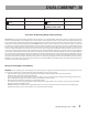
Wire Color Function Wire Color Function
*Red
Positive
*Black
Negative
*
Indicates a main power
cable
NOTE: All cables (except
Negative) contact +VDC
Instructions for Mounting, Wiring and Programming
IMPORTANT! To ensure proper installation installers are required to have a good understanding of automotive electronic, systems and procedures
for proper installation. When you are drilling into the vehicle’s surfaces, ensure that the area is free of any electrical wires, vehicle upholstery, fuel
lines, etc. that could be damaged. All wiring passing through drilled holes should use grommets and silicone sealant to prevent wire or moisture
damage when passing through compartment walls. WARNING! Larger wires and secure or tight connections will ensure longer service life for
your product. It is highly recommended that soldered connections have heat shrink used to protect the connection. Special attention should
be given to the location and method of splicing wiresto make electrical connections to protect these splices from lost power or connection and
corrosion. Insulation displacement connectors are not to be used. To reduce voltage drop, minimize the number of splices in the wires. The cur-
rent carrying capacity of wires and fuses will be signicantly reduced under high ambient temperature (e.g. under the hood). Use SXL type wire
in the engine compartment where higher heat resistance is required according to SAE J128. All wires should be in accordance with the minimum
wire size and other recommendations made by the manufacturer and be protected from hot surfaces and moving parts. Grommets, cable ties,
looms, and other installation hardware should be used to anchor and protect all wiring. Fuses should be properly sized and located as close to
the power take o points as possible to protect the wiring and device. To protect against short circuits, a fuse is included by STL for all products.
Do NOT use a fuse with a higher amp rating than the initial fuse included. Do NOT use Circuit Breaks with STL Products. Ground terminations
should only be made directly to the battery.
Wiring: Connecting Wires to the Battery
WARNING! If you are supplying your own wiring that connects to the positive or negative terminal of the battery, fuse sizes must be sized accord-
ing to STL’s provided fuse to be considered fused properly to the battery in order to carry the load.
• Route the power cables by opening the wiring shield and running the cables through it towards your vehicle’s rewall.
• Follow the factory wiring harness through the rewall.
• If it is necessary to drill a hole in the rewall for the power cables, be sure no components will be damaged from drilling. As with all holes
that are drilled, le the edges down smooth and insert a grommet to protect the cables.
• Route the cable along the factory wiring harness towards the battery.
• You will want to ensure your grounding cable is taken directly to the negative terminal of your battery to avoid any electrical feedback
which may disrupt your Light Bar system.
• DO NOT allow the positive (Red wire) and negative (Black wire) to touch one another. This may cause injury to you and damage your
equipment by causing a short in the unit that is not covered under the STL warranty.