
NX10 2.4GHz DSMX 10-Channel Radio System Manual

33SPEKTRUM NX10 • TRANSMITTER INSTRUCTION MANUAL
EN
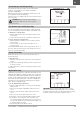
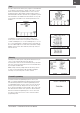
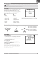
Curve Mix
If you want to be able to assign the output channel to respond on
a curve or act as a switch, the Curve mix option will enable you
to move the output channel to any value at up to 7 points along
the travel of the input channel. Below the curve values, select a
channel for master control on the left and slave on the right. For
example, Throttle > Rudder makes Throttle the master channel
and Rudder the slave channel.
A channel monitor at the bottom of the screen shows how
channels respond to input during setup. To view a mix on the
monitor, the mix switch must be in the active position or the switch
set to ON.
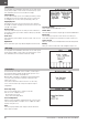
Trim
If the master channel trim should also adjust the slave channel, set
Trim to Act.
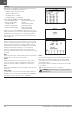
Curve
The Curve value corresponds to each page of values assigned to
a switch position. Leave the Curve value matching the highlighted
box below the switch position for a basic configuration.
Switch
Select the switch you wish to use to activate the mix. The black
box indicates the switch position where the currently displayed
curve page is active, and the tick below the boxes indicates the
current switch position.
Select ON if you wish to activate the mix full time and do not want
to use a switch.
TIP: Use Auto Switch Select to select the switch.
CAUTION: Always do a Control Test of your model after
changing mixes.
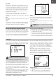
Curve (Page) Advanced Configuration Options
The Curve selection in either Normal or Curve mixes can enable
you to set up to 9 different settings pages. Curve settings within
one mix do not carry over to other mixes. This can be useful if you
want to test mixes and not have delete current configurations, or
can come into play when using numerous flight modes, with this
option there can be a separate mix page for each flight mode.
To select the page you want to adjust:
1. Assign the switch and begin with your first switch position.
2. Scroll to the Curve option and change the value to the number
you want for that Curve (page).
3. Scroll to the box above the active switch position and press the
scroll wheel to assign the Curve (page) to that switch position.
4. Move the switch(es) to the next position you want to configure,
select the Curve (page) you want to use, and repeat the process.
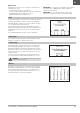
The Sequencer menu option provides this-then-that mixing with a time
delay. Four sequences are available to control two functions each (A
and B), in 2 timing directions (forward or reverse). Sequences appear
throughout function screens as assignable switches.
CAUTION: Always review the action of a sequence on
the Monitor screen BEFORE operating the model to
ensure controls act as desired. Failure to do so could cause a
crash, resulting in property damage and or injury.
You can program multiple functions to sequentially activate in
response to an assigned switch. For example, an assigned Gear
switch can open gear doors, lower the gear, then close the doors. In
reverse, gear doors open, the gear retracts and the gear doors close.
You can assign each Sequencer function to a switch in most
Function screens such as Flight Mode, Dual Rate, Mixing, Throttle
Curve, Pitch Curve, etc.
You can assign several functions to a sequence to decrease the number
of controls you need to touch during complex flight transitions—for
example, applying your assigned dual rates and exponential when the
landing gear deploys and the flight mode changes.
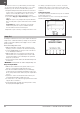
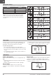
If you select an S-Number-A sequence (e.g. S3A), the sequence
operates as a timed 5-position switch. An S-Number-B sequence
operates as a timed 3-position switch. The 5 positions correspond
to the sequencer values shown on the time delay graph in the
second Sequencer screen. In a function screen, highlight each
point (0–4) and select the switch position desired for a function to
be active.
When S1B (or another sequence-number-B) is selected as
a switch in a function, the sequence will operate as a timed
3-position switch. The 3 positions act as ‘kick points’ of the
movement at fixed percentages (equal thirds) of the sequencer
output. In a function screen, highlight each point (0–2) and select
the switch position desired for a function to be active.
Sequencer Set Up
1. In the first Sequencer screen, select 1 of the 5 available
sequences.
2. In the second Sequencer screen, assign a switch to the
sequence. We recommend using a 2-position switch.
Sequencer