Table of Contents Handheld Unit ..................................................................................3 Installing the Battery .........................................................................4 Binding the Handheld Unit ...............................................................5 Real Time Information Screen...........................................................6 Store Lap ..........................................................................................7 Recall Lap......
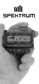
Handheld Unit The handheld unit displays real time information plus it can store and recall lap times, display maximum temperature, maximum speed and maximum rpm. Normally the pitman monitors the handheld unit and then informs the driver of critical information as needed. Mounting posts are included that can be installed in the open antenna hole in module radios allowing the handheld to be easily read by the driver.
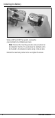
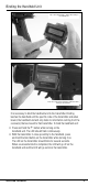
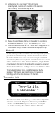
Installing the Battery Using a 3/32" and .050" hex wrench, unscrew the case and install a 9-volt battery as shown. Note: If desired, the mounting post (two sizes provided) can be installed at this time. The post allows the handheld unit to be mounted in the antenna hole when using a module radio. Reinstall the case being careful not to over-tighten the screws.
Binding the Handheld Unit Step 1: Press and hold the button while turning on the handheld unit. Step 2: Press and hold the transmitter’s bind button while turning on the transmitter It is necessary to bind the handheld unit to the transmitter. Binding teaches the handheld unit the specific code of the transmitter and when bound, the handheld unit will only listen to information coming from the receiver(s) that are bound to that transmitter.
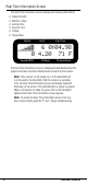
Real Time Information Screen The Real Time Information screen displays the following information • • • • • • Signal strength Number of laps Last lap time Speed or rpm Voltage Temperature Signal Lap # Lap Time � � � �� �� �� �� � ���������� ���������������� Speed/RPM Voltage Temperature The Real Time Information screen is displayed automatically when the system is turned on and the handheld unit connects to the receiver.
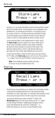
Store Lap Signal Lap # Lap Time ������������ �������������� Speed/RPM Voltage Temperature During a run, current lap information is stored in the telemetry module. (Not in the handheld unit). This information is then displayed on the handheld unit. To reset the lap information, it is necessary to turn the receiver off then on. This will reset the lap information and the screen will display 0 laps at 0:00.00 seconds. Previous laps will remain in memory of the handheld unit until it is power cycled.
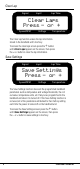
Clear Lap Signal Lap # Lap Time ������������ �������������� Speed/RPM Voltage Temperature The Clear Lap function erases the lap information stored in the handheld unit's memory. To access the clear laps screen press the button until Clear Laps appears on the screen, then press the + or- button to clear the lap information.
Roll Out Signal Lap # Lap Time �������� ���� Speed/RPM Voltage Temperature The Roll Out function is the internal calculator that allows rpm data to be converted to mph. When the Roll Out value is set to 1.00, the default setting, the value displayed on the main screen and stored in maximum speed, is true rpm of the shaft gear or flywheel that the rpm sensor is hooked up to. In order to program the unit to display speed in mph, a conversion factor is needed.
• Set the car next to a ruler and at 0" then roll the car forward by hand, counting each revolution of the reference mark. At exactly 10 revolutions stop the car. • Measure the exact distance that the car traveled in ten revolutions and divide this distance by 10 (i.e. 12.0" divided by 10 = 1.20"). • In the Roll Out screen press the + or – button until 1.20 appears on the screen. Now all the rpm related functions will be displayed in mph.
Maximum Temperature Signal Lap # Lap Time ������������ ����� Speed/RPM Voltage Temperature The Maximum Temperature screen displays the maximum achieved temperature from the point that the receiver/ telemetry module was turned on. To reset the maximum temperature, it is necessary to turn off the receiver/ telemetry module, then back on. To access the Maximum Temperature screen, press the button until the Maximum Temp appears.
Best Lap Signal Lap # Lap Time �������� ���������� Speed/RPM Voltage Temperature The Best Lap screen displays the fastest lap from the point that the receiver/ telemetry module was last turned on. The display gives the lap number and the fastest lap time. To reset the fastest lap, it is necessary to turn off the receiver. To access the Best Lap screen, press the button until Best Lap appears on the screen.
Battery Threshold Signal Lap # Lap Time �������������� ���� Speed/RPM Voltage Temperature The Battery Threshold screen allows you to preset a voltage. When the battery voltage in your vehicle drops below the preset voltage, the vibration alarm in the handheld unit will activate. Typical recommended preset values are 1.1 volts per cell, however, when using high current draw servos it may be necessary reduce that value to .9 volts per cell. Recommended voltage settings: • 5-cell 6.0 volt pack = 6.
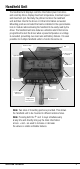
Installing the Unit in Your Vehicle Telemetry Module Telemetry Port RPM/Speed Port Temperature Port Lap Timer Port The telemetry module is used to interface the sensors to the receiver (transceiver). The module is attached to the receiver via the included male-to-male telemetry lead provided. The telemetry lead must be plugged into the BAT/TEL port in the receiver and into the T battery port in the module. See photo of receiver and telemetry hooked up with cord.
Signal and Battery Voltage Signal strength and battery voltage is built into the telemetry module and no further attachment of sensors is necessary. The telemetry module must be properly hooked up to the receiver, and with the handheld unit and receiver bound together. Signal strength and battery voltage will be displayed when the receiver and handheld units are turned on.
RPM/Speed Sensor (Nitro) An infrared sensor is provided to record rpm values that can be converted by the handheld unit to actual speed in mph. The sensor emits an infrared light and a receptor records the reflection vs. the absorption of light. It is necessary to place a reflective or light absorbing decal (provided) on the gear or flywheel to allow the sensor to record rpm. Mounting hardware is provided for easy installation.
• Install the mount under the engine screw and adjust the sensor so it is 1/8" from the flywheel. • If the flywheel is reflective (bare metal), place a flat black decal on the flywheel so it passes between the sensor and the flywheel when rotated. If the flywheel is non-reflective, place a reflective decal on the flywheel so that it passes between the sensor and the flywheel when rotated. • Plug the sensor into the R (speed/rpm) port in the telemetry module.
RPM/Speed Sensor (Electric) In electric cars and trucks, the rpm sensor is mounted near the spur gear and gets rpm readings directly from that gear. A conversion in the handheld can be programmed to give speed in mph or rpm. See the Handheld Unit section on rpm and speed for more details. A mount is provided that allows the rpm sensor to be conveniently mounted in many applications.
Temperature Sensor (Nitro) A temperature sensor loop is provided in the nitro system that wraps around the head of the engine to monitor head temperature. This is useful in tuning engines and in preventing damaging over-lean runs. Temperature Sensor Installation (Nitro) • Install the loop as shown around the cylinder of the engine. It is best to place the sensor near the point at which the head meets the cylinder to get the most accurate consistent readings.
Lap Counter/Timer The lap counter records and displays the number of laps and lap time for up to 99 laps. In order to use the lap timer, an optional lap trigger must be used. The lap counter/timer system utilizes an infrared sensor in the car and the lap trigger projects an infrared light across the track that triggers the sensor when the car passes. A Lexan mount is provided to allow easy mounting of the lap counting sensor in your vehicle.
Lap Trigger The Lap Trigger is placed next to the track and projects an infrared beam of light across the track that triggers the infrared sensor in the car each time it passes. The receiver records each lap time and sends that information to the handheld unit where it is displayed. Laps can then be stored and recalled from the handheld unit plus the fastest lap is displayed. A programmed delay of 2 seconds prevents double lap counts.
Attention Although this product is designed for ease of use, it is not a toy and requires some basic mechanical ability and adult supervision. This Manual contains basic instructions for safety, operation and maintenance. It’s essential to read and follow all the instructions and warnings in this manual, prior to assembly, setup or use, in order to operate correctly and avoid damage or injury. Safety Precautions This is a sophisticated product that must be operated with caution and common sense.
If you as the purchaser or user are not prepared to accept the liability associated with the use of this product, you are advised to return this product immediately in new and unused condition to the place of purchase. Questions or Assistance For questions or assistance, please direct your email to productsupport@horizonhobby.com, or call 877.504.0233 toll free to speak to a service technician.
© 2005 Horizon Hobby, Inc. 4105 Fieldstone Road Champaign, Illinois 61822 (877) 504-0233 horizonhobby.