Instruction Manual Bedienungsanleitung Manuel d’utilisation Manuale di Istruzioni
About Quique t began in Argentina with his father, Mario. Throughout the late 1970’s, Mario Somenzini was the reigning F3A Champion of Argentina and most of South America. As a boy, Quique would spend hours with his father at the flying field cleaning airplanes, watching and learning. It paid off. I In 1976, Quique made his first RC solo flight at the age of 9. Just three years later, he followed in his father’s footsteps and won his first Argentina F3A National Championship.
Sol de Mayo he Sol de Mayo (Sun of May) symbol on the SpektrumTM DX18QQ transmitter case comes from the national flag of Quique’s native country of Argentina. It’s just one of the many personal touches that Quique and the Spektrum team have included to make the DX18QQ unlike any transmitter you’ve flown with before. T ongratulations on the purchase of your DX18QQ! I’m very excited about this transmitter.
NOTICE All instructions, warranties and other collateral documents are subject to change at the sole discretion of Horizon Hobby, Inc. For up-to-date product literature, visit horizonhobby.com and click on the support tab for this product.
General Notes • • • • • Models are hazardous when operated and maintained incorrectly. Always install and operate a radio control system correctly. Always pilot a model so the model is kept under control in all conditions. Please seek help from an experienced pilot or your local hobby store. Contact local or regional modeling organizations for guidance and instructions about flying in your area. • When working with a model, always power on the transmitter first and power off the transmitter last.
Table of Contents System Overview Transmitter Batteries ................................................................................... 8 Charging Your Transmitter ..............................................................................8 Transmitter Functions ............................................................................... 10 Main Screen ............................................................................................... 12 Navigation .....................................
ACRO (Airplane) ................................................................... 45 Aircraft Type ...............................................................................................45 Recommended Servo Connections ...............................................................45 Elevon Servo Control ...................................................................................46 Flap System ................................................................................................
Transmitter Batteries Battery and Charging Precautions and Warnings Failure to exercise caution while using this product and comply with the following warnings could result in product malfunction, electrical issues, excessive heat, FIRE, and ultimately injury and property damage.
LED indicators The blue LED indicates the transmitter battery is charging. The orange LED indicates the transmitter is powered on and there is radio transmission. Battery Alarm The System Settings Screen allows you to change the battery type and low alarm settings. See “System Settings” for more information. • An alarm will sound when the battery reaches the low voltage limit (4.3V for NiMH, 6.4V for LiPo). CAUTION: Never change the low voltage limit for LiPo batteries from 6.4V.
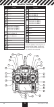
Transmitter Functions Function Function 1 Antenna 1 16 Back Button 2 RIght Trim 17 Speaker Grill 3 Right Knob 18 Rudder Trim (Mode 1,2) Aileron Trim (Mode 3,4) 4 Switch E 19 5 Switch H Elevator Trim (Mode 1,3) Throttle Trim (Mode 2,4) Switch G 20 6 7 Switch F Elevator/Rudder Stick (Mode 1) Throttle/Rudder Stick (Mode 2) Elevator/Aileron Stick (Mode 3) Throttle/AileronStick (Mode 4) 8 Throttle/Aileron Stick (Mode 1) Elevator/Aileron Stick (Mode 2) Throttle/Rudder Stick (Mode 3) Elev
Function Function 1 Throttle Spring Tension Adjustment (Mode 2,4) 8 Throttle Spring Tension Adjustment (Mode 1,3) 2 Left Lever 9 Right Rear Grip 3 Left Rear Grip 10 Right Lever 4 Trainer Port 11 Gimbal Stick Tension Adjustment 5 SD Card 12 Handle/Antenna 2 6 Battery Cover 13 Mode Change 7 Charge Port 13 12 1 11 2 10 3 9 4 8 7 5 6 www.spektrumrc.
Main Screen Function A Model Memory B Model Name C Transmitter Battery Charge Level D Digital Battery Voltage (an alarm sounds and the screen flashes when battery charge gets down to 4.3V when using an NiMH battery or 6.4V for a LiPo battery.
Navigation • Turn the scroll wheel to move through the screen content or change programming values. Press the scroll wheel to make a selection. • Use the Back button to go to the previous screen (for example, to go from the Mixing Screen Press Turn Hold to the FuncHold for 3 Enter, Choose Move between tion List). options or change seconds and or Exit value in an option release to move to • Use the the Main Screen Clear button to return a selected value on a screen to the default setting.
Binding Binding is the process of programming the receiver to recognize the GUID (Globally Unique Identifier) code of a single specific transmitter. The DX18QQ and AR12120 are pre-bound at the factory. You will need to rebind after the model programming is initially set up to fully program the model’s failsafe positions. Binding Using the Receiver and Receiver Battery (mode 2 shown) Hold button while powering on 1. 2. 4. 5. 3. 6. 1.
Programming Failsafe Positions You establish failsafe positions when you bind your transmitter and receiver. If the radio signal connection is lost between the transmitter and receiver, the receiver immediately moves the aircraft control surfaces to the failsafe positions. The Spektrum AR12120 receiver has three failsafes programming options: SmartSafe, Hold Last Command, and Preset.
X-PlusTM 8 The X-Plus 8 module is designed to allow expansion of up to 8 servos for noncontrol surface functions such as bomb drops, lights, winches, retractable landing gear, and many more. The X-Plus 8 is compatible with Spektrum™ X-Plus transmitters and receivers. The X-Plus 8 module offers the option to power the connected servos via dual auxiliary battery ports with separate batteries and switch harnesses (sold separately) independent of the receiver.
X+6 Servo X+5 Servo X+4 Servo X+3 Servo X+2 Servo X+1 Servo To SRXL Port Auxiliary Battery Pack (optional) Jumper On/Off Switch Harness (optional) X+8 Servo X+9 Servo Power System Requirements Inadequate power systems that do not provide the necessary minimum voltage to the receiver during flight are the number one cause of in-flight failures.
X-Plus Channels and Failsafe Failsafe is not supported for servos connected to the X-Plus Module. We recommend that no failsafe should be expected or attempted for a servo connected through the X-Plus Module. However, servos connected to the X-Plus Module will hold last command in the event of a failsafe condition. To Activate X-Plus 1. Open the Frame Rate Menu in System Setup. 2. Scrolll to X-Plus and press the scroll wheel to activate. The X-Plus Inputs screen is now active in the Channel Assign menu.
SD Card Installing the SD Card The included SD Card enables you to: • Import (copy) models from another DX18QQ transmitter • Export (transfer) models to another DX18QQ transmitter • Update AirWare™ software in the transmitter To install the SD Card: 1. Power off the transmitter. 2. Remove the battery door. 3. Press the SD Card into the card slot with the card label facing upward. 4. Install the battery door.
Model Type Programming Guide Menu options show up on model type selection. These menu options vary between Model Types (Airplane Helicopter and Sailplane), but are identical for all models in that type. Subsequent aircraft type (Aircraft, Swashplate or Sailplane) selections make other menu options appear.
System Setup List: Model Select Model Type Model Name Sailplane Type F-Mode Setup Channel Assign Trim Setup Model Copy Model Reset Warnings Telemetry Preflight Setup Frame Rate Bind Trainer Analog Switch Setup System Settings Transfer SD Card www.spektrumrc.
Common System Setup FunctIons Model Select Model Select enables you to access any of the 50 internal model memory locations in the Model Select list. 1. Scroll to the desired model memory in the Model Select list. 2. When the desired model memory is highlighted, press the scroll wheel once to select the model. The transmitter returns to the System Setup List. Direct Model Access Press the Clear and Back buttons from the Main Screen or a telemetry screen to access Model Select.
F-Mode Setup Use the Flight Mode Setup menu to assign switches to flight modes. Mode Number of Switches Number of Flight Modes Aircraft Up to 3 5 Heli 3 (including Throttle Hold) 5 (including Throttle Hold) Sailplane Flight Mode Setup You can assign up to ten flight modes using any combination of up to three switches. You can also assign a priority switch. When the priority switch position is active, only the current flight mode is active, regardless of other switch positions.
Channel Assignment The Channel Assignment function allows you to reassign almost any receiver channel to a different transmitter channel. For example, the receiver gear channel could be re-assigned to the transmitter throttle channel. When X-Plus is active in the transmitter, the DX18QQ operates channels 11 and 12 (AUX 6 and AUX 7) on a 12-channel receiver. Channels 11 and 12 will have 22ms frame rate and 2048 resolution. X-Plus allows for up to 8 additional channels over the 10 primary channels. 1.
Trim Setup Use the Trim Setup screen to change the size of the trim step and the trim type. Trim Step Adjusting the trim step value determines how many “clicks” of trim you input each time you press the trim button. Changing the trim step value to 0 disables the trim for the channel. To change the trim step value: 1. Scroll to the trim step channel you wish to change. 2. Select the trim step value and scroll left or right to change the value. 3. Press the scroll wheel to save the selection.
Model Copy The Model Copy menu enables you to duplicate model programming from one Model List location to another. Use Model Copy to: • Sort the models in the Model List by brand, model type or power source • Save a default model copy before experimenting with programming values • Expedite programming for a model using a similar programming setup. IMPORTANT: Copying a model program from one model memory to another will erase any programming in the “To” model memory. To copy model programming: 1.
Telemetry Installing the optional telemetry module and sensors enables the display of aircraft performance data on the transmitter screen. You can also enable Data Logging to save a telemetry file on the SD Card and view the data in the Spektrum STiTM mobile application. Telemetry Settings Display Telemetry display options include: Tele: When you press the scroll wheel, the Telemetry screens appear and the Main Screen is disabled.
Preflight Setup The Preflight Setup menu option enables you to program a pre-flight checklist that appears each time you power on the transmitter or when you select a new model memory. Each item on the list must be confirmed before you can access the Main Screen. Frame Rate The Frame Rate menu enables you to change the frame rate, modulation mode and activate X-Plus. Select the option you wish to change and press the scroll wheel. Frame Rate You must use digital servos if you select 11ms frame rate.
Trainer The DX18QQ features a programmable trainer function with 4 trainer modes. The transmitter assigns the trainer function to Switch I. The 4 trainer modes include: Inhibit In Inhibit, the slave transmitter must have the same programming as the master transmitter (e.g., servo reversing, travel adjust, sub-trim, trims). Programmable Programmable mode enables you to program the master transmitter to transfer any or all individual channels when you activate the trainer switch.
Analog Switch Setup Allows all sticks and pots to be used as a kick point to turn on functions like mixes. To add a kick point: 1. Move the control stick, lever or knob to the desired kick point position. 2. Scroll to the desired kick point and press the scroll wheel once to save the selection. To delete a kick point, scroll to the desired kick point and press the Clear button. System Settings The System Settings menu consists of four screens: System Settings, Extra Settings, Serial Number and Calibrate.
Mode You can change transmitter modes among Modes 1, 2, 3 and 4. This conversion requires both a programming and a mechanical change. Please refer to Transmitter Mode Conversion on page 61 for directions on making the necessary mechanical changes. If mechanical changes are required for the mode you need to change to, complete the mechanical changes first, then follow the instructions below for the software setting change. To change the gimbal stick mode: 1. Scroll to Mode and press the scroll wheel. 2.
Inactive Alarm An alarm activates if the transmitter sees a period of inactivity for a certain amount of time. The alarm is helpful in reminding you to power off the transmitter and avoiding a situation when the transmitter battery completely discharges. The Inactive Alarm options are: • Inh (No alarm sounds) • 5 min • 10 min (Default) • 30 min • 60 min To change the Inactive alarm time: 1. Scroll to the current alarm time and press the scroll wheel. 2. Scroll left or right to change the alarm time.
Serial Number The Serial Number screen displays the transmitter serial number and AirWare software version. Reference the Serial Number screen any time you need to register your transmitter or update the AirWare software from the Spektrum Community website. Exporting the Serial Number to the SD Card You may find it helpful to export the transmitter serial number to a text file for your personal records or when you are registering the transmitter on the Spektrum Community.
Transfer SD Card Import Model To import an individual model file from the SD Card: 1. Save the model file to the SD Card. 2. Select the Model List location where you wish to import the new model file. 3. In the SD Card menu, scroll to Select Option and press the scroll button once. 4. Scroll to Import Model and press the scroll button again to save the selection. The Select File screen appears. 5. Select the model file you wish to import. The Overwrite screen appears.
Export All Models To export all models to the SD Card: 1. Select Export All Models in the SD Card Menu options. The Export All Models screen appears. IMPORTANT: Export All Models will overwrite any model files that: • Are already saved on the SD Card. • Have the same name. Always save model files to a different SD Card if you are not sure. 2. Select Export to overwrite files on the SD Card or Cancel to return to the SD Card Menu.
Function List Servo Setup The Servo Setup menu contains the following functions: • Travel Adjust • Sub-Trim • Reverse • Speed • Abs. (Absolute) Travel • Balance Travel Adjust Travel Adjust sets the overall travel or endpoints of the servo arm movement. To adjust travel values: 1. Scroll to the channel you wish to adjust and press the scroll wheel. When adjusting travel values assigned to a control stick: Select this when X-Plus a.
Speed The Speed menu enables you to increase the response time on any individual channel (such as retracts). The Speed is adjustable in the following ranges: • Nor (No Delay) — 0.9s in 0.1 second increments • 1s – 2s in 0.2 second increments • 2s – 8s in 1 second increments To adjust the Speed: 1. Scroll to the channel you wish to adjust and press the scroll wheel. 2. Scroll left or right to adjust the speed and press the scroll wheel to save the selection. Absolute (Abs.) Travel The Abs.
Differential (Air and Sail Types only) The Differential screen enables you to increase or decrease the amount of differential between aileron control surface throws. Positive Differential values decrease the amount of “down” travel without affecting the “up” travel on the opposite control surface. Negative Differential values decrease the amount of “up” travel without affecting the amount of “down” travel on the opposite control surface.
Throttle Curve You can use the Throttle Curve menu option to optimize the throttle response. A maximum of 7 points are available on the throttle curve. To add points to a Throttle Curve: 1. Move the throttle stick to the position where you wish to add the new point. 2. Scroll to Add Pt. and press the scroll wheel to add the point. To remove points from a Throttle Curve: 1. Move the Throttle stick until the cursor is near the point you wish to remove. 2. Scroll to Remove Pt.
Assigning a Mix to a Switch If you wish to assign a mix to a switch position: 1. Scroll to Switch and press the scroll wheel. 2. Scroll left or right to the switch you wish to use and press the scroll wheel to save the selection. 3. Scroll to the switch position where you want the mix to be active. The mix is Active when the box is filled and Inactive when the box is open. You can assign a mix to be active in multiple switch positions (0,1 or 2).
Origin Mixing Origin Mixing uses true stick position as the input for a mix. When origin mixing is selected, any other settings to the master channel will be ignored and the mix will be based strictly on stick position and trim position. When Aileron, Elevator, or Rudder are selected as the master, origin mixing is available. Once Aileron, Elevator, or Rudder are selected, an N will appear next to the master channel, where N means normal. Roll and select the N to change to O for origin mixing.
Sequencer Set Up 1. In the first Sequencer screen, select 1 of the 5 available sequences. 2. In the second Sequencer screen, assign a switch to the sequence. We recommend using a 2-position switch. Tip: If you need to use a 3-position switch, you must assign one direction to two adjacent switch positions—e.g., 0 and 1. Assign the opposite direction to the third switch position. 3. Assign the timing for the Forward and Reverse directions as desired. There is no delay when you use the Nor option.
Range Testing the DX18QQ 1. With the model restrained on the ground, stand 30 paces (approx. 90 feet/28 meters) away from the model. 2. Face the model with the transmitter in your normal flying position and place the transmitter into Range Test mode (see above) and push the trainer button, reducing the power output. 3. Operate the controls. You should have total control of your model with the transmitter in Range Test mode. 4.
Monitor The Monitor screen displays the servo positions for each channel graphically and numerically. This is useful to verify programming functions, trim settings, mix directions, etc. The numeric value is directly relative to the travel adjust and mix values (e.g., 100% travel adjust equals 100% value in the Monitor). X-Plus Monitor Use of the X-Plus Monitor requires X-Plus to be active. The X-Plus Monitor screen displays the output position for each X-Plus channel graphically and numerically.
ACRO (Airplane) Aircraft Type NOTICE: Refer to your airplane manual for recommended control throws. CAUTION: Always do a Control Test of your model with the transmitter after programming to make sure your model responds as desired. Use the Aircraft Type Screen to select wing and tail types to match your airplane model. Diagrams and setup names show on the transmitter screen to show the available setups. Refer to community.spektrumrc.
Elevon Servo Control The possible servo reversing options for a delta wing model are: Aileron Normal Normal Reverse Reverse Elevator Reverse Normal Reverse Normal Tip: If you test all servo reversing options and the control surfaces do not move in the correct direction, change the Elevon wing type in the System Setup list from Elevon-A to Elevon-B.
Flap System The Flap System menu option enables flap programming as well as elevator mixing. You must select a flap-enabled wing type in Aircraft Type or the Flap System menu does not appear. To activate the Flap System: 1. Access the System Setup list and select Aircraft Type. 2. Select a flap-enabled wing type and exit the System Setup list. 3. Access the Function List from the Main Screen and select Flap System. 4. Select Inhibit and scroll to the switch or lever you wish to use to control the flap channel.
Acro Gyro Function The Gyro menu option enables you to create up to 7 gyro gain points on a maximum of 4 curves. Gyro gain curves also provide flexibility in reducing gyro gain as the control stick moves farther away from the center. To access the Gyro screen 1. In the System Setup List, highlight Aircraft Type 2. In the Aircraft Type Screen, select NEXT at the bottom right of the screen. This will access the Aircraft Options screen. Activate the desired Gyro function(s).
HELI (Helicopter) NOTICE: Refer to your helicopter, gyro and governor manuals for programming recommendations. CAUTION: Always do a Control Test of your model with the transmitter after programming changes to make sure your model responds as desired. Swash Type The Swash Type menu option assigns the swash type for your particular helicopter model. Select the Swash Type before completing any programming in the Function List. The Swash Type will affect menu options in the Function List.
Swashplate The Swashplate menu option enables you to adjust the following: • Swashplate Mix • Exponential • E-Ring • Elevator Compensation Use positive or negative Swashplate mix values as needed for correct direction response of the helicopter. Before making adjustments to the Swashplate mix, make sure the throttle/collective pitch input moves the entire swashplate up or down. If the servos are not moving in the same direction, reverse them as necessary in the Servo Setup menu option.
Governor The governor function is used to set the rotor head speed when used with a governor installed in the helicopter. The governor onboard will control the engine RPM to maintain the head speed desired. You can program values for each switch position or flight mode. RPM values can be programmed in 0.5% steps. To Program the Governor Function: 1. Access the Governor menu option. 2. Program the RPM values by rotating the scroll wheel to the desired value. 3.
SAIL (Sailplane) Sailplane Type NOTICE: Refer to your sailplane manual for recommended control throws. CAUTION: Always do a Control Test of your model with the transmitter after programming to make sure your model responds as desired. Use the Sailplane Type Screen to select wing and tail types to match your sailplane model. Diagrams and setup names show on the transmitter screen to show the available setups. Refer to community.spektrumrc.
Camber System Camber System is only available when 2 or 4 aileron wing type is selected in Sailplane Type. The Camber System allows in-flight camber adjustment and is also used as the braking system, often referred to as Crow or Butterfly. The Camber System enables you to assign the Camber System to a different switch in each flight mode. SAIL Mixing For each of these mixes, you can program each flight mode with different mix values or at 0% if no mix is desired for that specific flight mode.
Receiver Installation And Power System Requirements The Spektrum AR12120 PowerSafe™ receiver offers the ultimate solution for powering high-current draw radio systems. In aircraft with multiple high-current draw servos (e.g. giant-scale aircraft, jets, etc.), the AR12120 receiver can provide peak current of up to 50 amps and offers true dual battery redundancy and a fail-on soft switch for the ultimate in reliability.
Specifications PowerSafe Main Unit Voltage input: 6.0 to 10.0 volts Minimum operational voltage: 3.5 volts Continuous current: 35 amps Peak current: 50 amps Resolution: 2048 Main unit dimensions LxWxH: 46.5 x 52 x 15.3mm Weight: 72 g Connector type: EC3 Regulator: None Remote Receiver Dimensions LxWxH: 25.8 x 20.2 x 6.8mm Weight: 3 g Battery Requirements Using One Battery The PowerSafe receiver allows the option of using one or two battery packs.
Recommended Guidelines for Battery Capacity 40–45% Aerobatic aircraft w/ 9–12 high-current servos: 4000–8000mAh 33–35% Aerobatic aircraft w/ 7–10 high-current servos: 3000–6000mAh 25% Quarter Scale Aerobatic aircraft w/ 5–7 high-current servos: 2000– 4000mAh Jets — BVM Super BANDIT, F86, Euro Sport, etc.
Installing the Batteries Using the given guidelines, select the battery system that best fits your application and install the battery(s)/regulator(s) in your aircraft. Connect the battery to the receiver. Spektrum batteries are pre-wired with an EC3 connector and plug directly in. If using another brand of battery, it will be necessary to solder EC3 connectors (two are included with the AR12120) to the battery leads. If using a regulator, install it per the guidelines included with the regulator.
Locating the Remote Receivers While Spektrum 2.
Failsafe Functions The AR12120 PowerSafe features two types of failsafe: SmartSafe™ and Preset Failsafe. SmartSafe Failsafe This type of failsafe is recommended for most types of giant-scale aircraft. Here’s how SmartSafe works: Receiver Power Only When the receiver only is turned on (no transmitter signal is present), all servos except for the throttle are driven to their preset failsafe positions, normally all control surfaces at neutral and the landing gear down.
Preset Failsafe: • Prevents unintentional electric motor response on start-up. • Drives all servos, except for the throttle to their preset failsafe positions, if the receiver only is powered and no signal is present. • Establishes preset failsafe servo positions for all channels if the signal is lost. Programming SmartSafe During the binding process, the bind plug is left in throughout the process and is removed only after the receiver connects to the transmitter.
Physical Transmitter Adjustments Transmitter Mode Conversion You can change transmitter modes among Modes 1, 2, 3 and 4. This conversion requires both a programming and a mechanical change. Programming Conversion: 1. Access the System Settings menu from the Setup List and select the desired Mode. 2. Exit the System Settings menu to save the selection. 3. Power off the transmitter and remove the transmitter battery pack.
Adjusting the Elevator Centering Screw When changing between Modes 1 and 2, or between Modes 3 and 4, you must adjust the elevator centering screw. 1. Hold the Elevator or Throttle stick in the full up or full down position when you are adjusting the elevator centering screw. Holding the gimbal stick reduces the load on the elevator centering mechanism and makes it easier to adjust the centering screw. 2. Locate the gimbal where the elevator centering spring is engaged.
Function 1 Throttle friction strip tension screws 2 Gimbal spring covers 3 Friction straps access screws (Changing the Throttle Ratchet) 1 2 3 Adjust Throttle Friction Straps To adjust Throttle Friction: 1. Pull up the top of the rear grip on the back of the transmitter to adjust the friction strip on the throttle gimbal. Only the top of the grip must be pulled up to access the adjustment screw. The entire grip does not need to be removed. 2.
2.
Problem Receiver loses its bind Receiver slowly blinking at landing (DSM2 Only) Possible Cause Transmitter stand or tray could be pressing the bind button Bind button pressed before transmitter powered on Loss of power to the receiver during flight System powered on and connected, then receiver powered off without powering off transmitter Poor signal reception Flight log registers undesirable number of fades, losses or holds or aircraft responds irregularly to controls Electronic feedback Low power So
AMA National Model Aircraft Safety Code Effective January 1, 2011 A. GENERAL A model aircraft is a non-human-carrying aircraft capable of sustained flight in the atmosphere. It may not exceed limitations of this code and is intended exclusively for sport, recreation and/or competition. All model flights must be conducted in accordance with this safety code and any additional rules specific to the flying site. 1. Model aircraft will not be flown: (a) In a careless or reckless manner.
B. RADIO CONTROL (RC) 1. All pilots shall avoid flying directly over unprotected people, vessels, vehicles or structures and shall avoid endangerment of life and property of others. 2. A successful radio equipment ground-range check in accordance with manufacturer’s recommendations will be completed before the first flight of a new or repaired model aircraft. 3.
FCC Information This device complies with part 15 of the FCC rules. Operation is subject to the following two conditions: 1. This device may not cause harmful interference. 2. This device must accept any interference received, including interference that may cause undesired operation. CAUTION: Changes or modifications not expressly approved by the party responsible for compliance could void the user’s authority to operate the equipment.
FAA Information Prior to flying, contact your local or regional modeling organizations for guidance and familiarize yourself with the current local rules and FAA regulations governing model aviation in your location. More information about model aviation can be found at www.modelaircraft.org. The Federal Aviation Administration can be found online at www.faa.gov. www.spektrumrc.
1-Year LIMITED WARRANTY What this Warranty Covers Horizon Hobby, Inc., (Horizon) warrants to the original purchaser that the product purchased (the “Product”) will be free from defects in materials and workmanship for a period of 1 years from the date of purchase.
Inspection or Services If this Product needs to be inspected or serviced and is compliant in the country you live and use the Product in, please use the Horizon Online Service Request submission process found on our website or call Horizon to obtain a Return Merchandise Authorization (RMA) number. Pack the Product securely using a shipping carton. Please note that original boxes may be included, but are not designed to withstand the rigors of shipping without additional protection.
Warranty and Service Contact Information Country of Purchase United States of America Horizon Hobby Address Phone Number/Email Address Horizon Service Center (Electronics and engines) 877-504-0233 Online Repair Request: visit www.horizonhobby.com/service Horizon Product Support (All other products) 4105 Fieldstone Rd Champaign, Illinois, 61822 USA 877-504-0233 productsupport@ horizonhobby.
Compliance Information for the European Union AT ES LT RO BE FI LU SE BG FR LV SI CZ GR MT SK CY HU NL UK DE IE PL DK IT PT Declaration of Conformity (in accordance with ISO/IEC 17050-1) No.
Notes © 2012 Horizon Hobby, Inc. The Spektrum trademark is used with permission of Bachmann Industries, Inc. DSM2, AirWare, SimpleScroll, JR, Vibe, X-Plus and Bind-N-Fly are trademarks or registered trademarks of Horizon Hobby, Inc. DSMX is a trademark of Horizon Hobby, Inc., registered in the US. SD Logo is a trademark of SD-3C, LLC US 7,391,320. Other patents pending. www.spektrum-rc.