®
Table of Contents Alternate Languages.........................................................................................................................3 Introduction.....................................................................................................................................3 ModelMatch/Binding.......................................................................................................................4 System Features...................................................
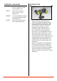
Alternate Languages Introduction ITALIAN: Per la versione italiana di questo manuale vi preghiamo di visitare il sito www.spektrumrc.com FRENCH: Pour consulter ce manuel en français, visiter le site www. spektrumrc.com GERMAN: Zur Ansicht der Bedienunsanleitung in den Deutsch besuchen Sie bitte www.spektrumrc.com SPANISH: Para ver este manual en Español entra en www.spektrumrc.com Spektrum’s DX3R was designed by top level racers to be the ultimate uncompromising racing radio.
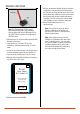
ModelMatch/Binding The DX3R features ModelMatch™ (patent pending). ModelMatch prevents a model from being operated using the wrong model memory. If the wrong model memory is selected, the receiver simply won’t respond to the transmitter preventing driving the car using the wrong model memory. It’s necessary to program the receiver to a specific model memory (called binding) so that the receiver will only recognize and respond to that specific model memory.
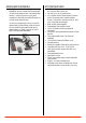
Installing the Batteries The transmitter requires 4 AA batteries: brand name alkaline AA’s providing over 15 hours of run time. Many racers prefer alkaline batteries over rechargeable batteries, finding it more convenient to simply replace the batteries when depleted rather than taking the time to recharge. Optional NiCd or NiMH 1.2-volt AA rechargeable batteries can also be used. A charge jack located below the on/off switch is provided for convenient recharging.
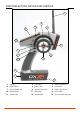
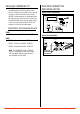
Identifying Buttons, Switches and Controls 1 8 2 7 9 10 14 3 4 13 15 5 12 6 11 1: Antenna 2: LCD Screen 3: Switch D/Steering Trim 4: Switch E/Brake 5: Button F/Timer 6: Charge Jack 7: Switch A/Throttle Trim 8: Switch B/Steering Trim 9: Switch C/Aux 3 Linear 10: Rolling Selector 11: Battery Door 12: On/Off Switch 13: Throttle Trigger 14: Steering Wheel 15: Steering Tension Adjustment 6 SPEKTRUM DX3R PROGRAMMING GUIDE
Note: The switches listed above are the factory default functions assigned to each switch.
Binding a Receiver 7. With the steering wheel, throttle stick and Aux channel (if applicable) in the desired preset failsafe positions, press the roller to initiate the bind process and to store the failsafe positions. BIND will flash for a few seconds then the transmitter will beep, indicating the process is complete. The LED on the receiver should now be solid, indicating a successful bind has taken place. 8. Remove the bind plug and store it in a convenient place.
Receiver Compatibility The DX3R features DSM2 technology but is also compatible with most DSM1 Spektrum surface receivers. When the fastest response rate is desired, using the system with a DSM2 receiver like the AR3100 is recommended as this combination gives the lowest possible latency/ quickest response rate. During the binding process the transmitter actually “learns” the receiver type (DSM1 or DSM2) and configures itself to transmit that protocol.
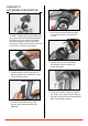
Changing to Left-Handed Configuration The DX3R is shipped set up for right-handed use but can easily be switched to left-handed configuration. All the parts necessary to convert to left-handed, including the grip plates, the back cover and the front shell are included. A 3/32-inch hex wrench and a small Phillips screwdriver will be needed. 3. U se a 3/32inch hex wrench remove the three screws on the front of the steering housing as shown. 4.
6. Carefully pull out the grip plate that contains buttons D, E and F. Use a Phillips screwdriver remove the PC board and backplate from the grip plate. Note the positions of the three buttons. 7. Transfer the three buttons (D,E and F) to the other “handed” grip plate noting that the buttons fit in a specific direction such that they fit the external contour of the grip plate. 9. P lace both grip plates in place and fasten them using four Phillips screws (two per side). 10.
Using the Rolling Selector 12. Connect the steering wheel mechanism connector to the connector from the transmitter being sure the connection is tight. Note correct polarity. The Rolling Selector is pressed to access functions and rolled to selected specific features or to change setting or values. Pressing and holding the rolling selector for more that 3 seconds returns the display to the main screen. The DX3R features one-touch programming utilizing a Rolling Selector.
Main Screen List List 7 Racer X 01: Losi Eight Int 1:47:30 Dn Tmr 05:00 8 9 1 2 4.
Model Model Select Model ≤ Model ≤ Name: Model 01 Name: Model 01 Copy To: 02: Model 02 The Model screen offers three functions: Model Select: Allows the selection of one of thirty model memories. This allows you to store and select up to thirty models. Model Name: Allows the selected model to be given a name with up to ten characters. Model Copy: Allows a model memory to be copied internally to a different model memory (i.e. model one (01) can be copied to model thirty (30)).
Model Name Model Name ≤ ◊ Name: Model 01 To access the Model Name function: In the Model screen, use the roller to highlight the Name function. A box will surround the Select function. Press the roller to access the Name function. The above screen will appear. Use the roller to select the desired model name character position by placing the cursor below the desired position. Press the roller to access that character or number; then use the roller to change to the desired letter or number.
Model Copy Model ≤ Name: Model 01 ◊ Select: 01: Model 01 Copy To: 02: Model 02 To access the Model Copy function: In the Model screen use the roller to highlight the Copy To function. A box will surround the Copy To function. Press the roller to access the Copy To function. The box will now be flashing, indicating the Copy To function has been selected.
Travel Travel ≤ User Name 01: Model 01 ST TH AX L R H L H L 100% 100% 100% 100% 100% 100% The Travel screen (sometimes referred to as travel adjust or end points) allows independent travel adjustment of the servo throw in each direction of all three channels (steering, throttle and auxiliary). A graphic illustration displays the effect of travel adjust. To access the Travel function: From the list screen rotate the roller to highlight the Travel function.
Steering Rate ≤ Steer Rate User Name 01: Model 01 S/R 100% S/R Override INHIBIT To access the Steering Rate function: In the List screen use the roller to highlight the Steering Rate function. Press the roller to access the Steering Rate function. The above screen will appear. Use the roller to select the S/R function or the S/R Override function by placing the box around the desired function. Press the roller to access S/R or S/R Override; then use the roller to change to the desired Steering rate value.
Exponential ≤ Expo User Name 01: Model 01 ST TH AX L R H L H L 0% 0% 0% 0% 0% 0% Exponential is used to affect the response rate of the steering, throttle and/ or brake. Typically positive Exponential is used for steering, reducing steering sensitivity around neutral, making it easier to drive the car at high speeds in a straight line but exponential still allows for the maximum turning radius.
Sub Trim Reverse ≤ ≤ Reverse Sub Trim User Name 01: Model 01 User Name 01: Model 01 ST TH AX REV NOR The Reverse function (also know as servo reverse) establishes the servo’s direction relative to the channels input (i.e. a right steering input should result in a right steering angle at the car). Reverse is available on all three channels and is normally the first function that is checked and adjusted during programming.
Timer Down timer: ≤ Timer User Name 01: Model 01 Internal Reset Int 0:08:19 Timer A: Int 0:08:18 Timer B: Dn Tmr 05:00 The DX3R offers three types of timers: Internal timer: Automatically records the time that the transmitter is turned on. Timer A is defaulted to the internal timer. Up timer: The Up Timer is triggered via a selectable button/ switch and counts up from 00:00 seconds, functioning as a stopwatch.
ModelMatch Bind ≤ Bind User Name 01: Model 01 Place the RX into bind mode first. BIND The DX3R features patented ModelMatch technology that prevents operating a model using the wrong model memory. During the binding process, the receiver actually stores the code that is assigned to the specific model that is currently selected in the transmitter.
Failsafe ≤ Bind User Name 01: Model 01 Place the RX into bind mode first. Failsafe positions are also set during binding. In the unlikely event that the radio link is lost during use, the receiver will drive the servos to their preprogrammed failsafe positions (normally full brakes and straight steering). If the receiver is turned on prior to turning on the transmitter, the receiver will enter the failsafe mode, driving the servos to their preset failsafe positions.
Frame Rate ≤ Frame Rate To access the Frame Rate function: In the List screen, use the roller to highlight the Frame Rate function. User Name 01: Model 01 Press the roller to access the Frame Rate function. The above screen will appear. CAUTION: Use the roller to select and highlight Frame Rate: at the bottom of the screen. Digital servos must be used with 5.
Mixing The mixing function allows any of the channels (steering, throttle and Aux.) to be mixed to any channel. Two mixes are available, Mix A and Mix B. Both mixes function identically. Typically this is used for dual steering servos in giant-scale trucks or for dual throttles in dual engine boats. The primary or controlling channel is called the master while the channel that is mixed to is called the slave.
Reset Trim Step ≤ ≤ Reset Trim Step User Name 01: Model 01 Steering 4 Throttle 4 Model 01: Model 01 User Name Parameters The Trim Step function allows the user to adjust the sensitivity of the steering and throttle/brake trims. It’s important to understand that Trim Step affects the amount the servo travels with each click of the trim but has no effect on the total trim travel.
≤ ≤ Confirm Calibrate Reset 01: Model 01 Cycle Controls SAVE NO YES Use the roller to highlight YES; then press the roller to reset. To return to the Main screen press and hold the roller for more than three seconds. To access the Parameters (recalibrate) function: CH1- 2015 CH1 2019 CH1+ CH2- 2025 2240 CH2 2240 CH2+ 2241 Rotate the steering wheel full right then full left; then move the throttle trigger to full throttle and full brake.
System Monitor ≤ Monitor User Name 01: Model 01 ≤ System Switch Select A B C D E F Username User Name +129 TH +0 Contrast: 10 +0 Voltage Alert 4.0v AX A servo monitor is available that displays the servo output positions graphically and digitally. This monitor can be useful in troubleshooting setups, displaying mixing functions and how they interrelate, etc. ◊ ST The System function allows the six available switches (A,B,C,D,E and F) to be programmed to the desired function.
User Name Switch Select The Switch select function allows any of the six available switches (A, B, C, D, E and F) to be assigned one of the following functions: A user name with up to ten characters can be programmed and the name is displayed on the Main screen. To program a user name: ≤ Switch In the System screen highlight the User Name and press the roller to access the function.
General Notes Radio controlled models are a great source of pleasure. Unfortunately, they can also pose a potential hazard if not operated and maintained properly. It is imperative to install your radio control system correctly. Additionally, your level of operating competency must be high enough to ensure you are able to control your model under all conditions. If you are a newcomer to radio controlled models, please seek help from an experienced modeler or your local hobby shop.
Safety Precautions (c) Purchaser Remedy- Horizon’s sole obligation hereunder shall be that Horizon will, at its option, (i) repair or (ii) replace, any Product determined by Horizon to be defective. In the event of a defect, these are the Purchaser’s exclusive remedies. Horizon reserves the right to inspect any and all equipment involved in a warranty claim. Repair or replacement decisions are at the sole discretion of Horizon.
Inspection or Repairs If this Product needs to be inspected or repaired, please call for a Return Merchandise Authorization (RMA). Pack the Product securely using a shipping carton. Please note that original boxes may be included, but are not designed to withstand the rigors of shipping without additional protection. Ship via a carrier that provides tracking and insurance for lost or damaged parcels, as Horizon is not responsible for merchandise until it arrives and is accepted at our facility.
Safety, Precautions, and Warnings As the user of this product, you are solely responsible for operating it in a manner that does not endanger yourself and others or result in damage to the product or the property of others. Carefully follow the directions and warnings for this and any optional support equipment (chargers, rechargeable battery packs, etc.) that you use. This model is controlled by a radio signal that is subject to interference from many sources outside your control.
FCC Information FCC ID: BRWDAMTX10 IC: 6157A-BRWDAMT This device complies with part 15 of the FCC rules. Operation is subject to the following two conditions: (1) This device may not cause harmful interference, and (2) this device must accept any interference received, including interference that may cause undesired operation. Caution: Changes or modifications not expressly approved by Horizon Hobby, Inc. could void the user’s authority to operate the equipment.
Operating and Programming Notes: SPEKTRUM DX3R PROGRAMMING GUIDE 35
® © 2007 Horizon Hobby, Inc. 4105 Fieldstone Road Champaign, Illinois 61822 (877) 504-0233 horizonhobby.