® DSM Sport System with Integrated Telemetry
Table of Contents Introduction.............................................................................................................................................3 Contents..................................................................................................................................................3 ModelMatch/Binding...............................................................................................................................3 System Features.....................
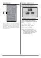
ModelMatch/Binding The DX3S features ModelMatch (patent pending). ModelMatch prevents a model from being operated when the wrong model memory is selected. If the wrong model memory is selected the receiver simply won’t respond to the transmitter. Introduction Spektrum’s DX3S features an integrated telemetry system providing accurate speed/rpm, temperature and voltage readings. Featuring DSM 2.
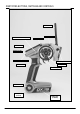
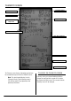
Identifying Buttons, Switches and Controls Antenna Steering Trim Switch - Aux. Ch.
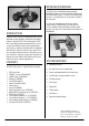
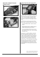
Switching Rubber Grips The DX3S is supplied with 3 different sized rubber grips with the medium size installed on the transmitter. Each grip’s size is identified with an “S” (small), “M” (medium), or “L” (large) on the inside of the grip for easy identification. To remove, simply lift the edge of the grip and continue around the grip until it is completely removed. To replace, align the tabs of the grip to the slots in the handle and press the grip in place.
Steering Rate Receiver Compatibility The DX3S features DSM technology and is also compatible with most DSM Spektrum surface receivers. Steering Rate Compatible Spektrum Receivers Steering rate, (also known as dual rate) allows on-the-fly steering travel adjustments to be made using the steering rate knob. Steering rate limits the amount of travel of the steering servo. The steering rate cannot be greater than 100% and will never exceed the amount of steering travel set in the travel screen.
Receiver Connection and Installation Using the Rolling Selector Rolling Selector Typical Electric Installation The Rolling Selector is pressed to access functions and rolled to select specific features or to change settings or values. Pressing and holding the Rolling Selector for more than 3 seconds returns the display to the main screen. The DX3S features one-touch programming utilizing a Rolling Selector. The Rolling Selector has three functions: 1.
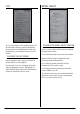
Main Screen Model Number and Name Down Timer Internal Timer Transmitter Voltage Steering Rate Brake Trim Steering Trim Throttle Trim Auxiliary Trim The main screen displays pertinent information about the selected model like trim and steering rate positions, timers, the model selected, battery voltage, etc. To access the main screen From the List screen, the first function at the top of the List screen is MAIN.
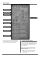
Telemetry Screen Model Number Transmitter Voltage Down/Up Timer Maximum Recorded Temperature Signal Strength Maximum Recorded rpm/Speed Real-Time rpm/Speed Receiver Battery Voltage Temperature Alert Temperature The Telemetry screen displays information received from the on-board telemetry built into the SR3300T receiver. Note: The signal strength display is for the Telemetry link only. Typical telemetry range is 100–200 feet and will vary depending on the operating environment.
List The List screen displays all the available functions. The desired function can be accessed by highlighting the desired function using the Rolling Selector and, when highlighted, pressing the Rolling Selector to enter the function. To access the List screen From the telemetry or main screen press the Rolling Selector until the List screen appears. From any other screen, List is located at the top right side of the programming screens.
Model Name To access the Model Name function In the List screen rotate the Rolling Selector to highlight the model name function. Model Reset The Model Reset function is used to reset the current model memory to the factory defaults. To Access the Reset Function Press the Rolling Selector to access the Model Name function. The above screen will appear. In the List screen use the Rolling Selector to highlight the Model Reset function then press the Rolling Selector.
Travel Press the Rolling Selector to enter the highlighted channel’s travel function. Rotating the Rolling Selector will now adjust both the upper and lower values simultaneously. If you desire to adjust the upper or lower directions independently then move the corresponding channel’s wheel, throttle trigger, or switch that the channel is assigned to and that value alone will be highlighted.
Exponential To access the Exponential function From the list screen use the Rolling Selector to highlight the Exponential function. Press the Rolling Selector to enter the Exponential function. The Expo screen will be displayed as shown on this page. Rotate the Rolling Selector and highlight the values next to the desired channel you wish to adjust. ST= Steering TH= Throttle and brake Press the Rolling Selector to enter the highlighted channel’s Expo function.
Reverse Sub Trim The Reverse function (also known as servo reversing) establishes the servo’s direction relative to the channel’s input (e.g. a right steering input should result in a right steering angle at the car). Reverse is available on all three channels and is normally the first function that is checked and adjusted during programming. The Sub Trim function is normally used to correct minor angular inaccuracies that occur when placing the servo horn on the servo.
Timer To access the Timer function From the list screen rotate the Rolling Selector to highlight the Timer function. Press the Rolling Selector to enter the Timer function. The Timer screen will be displayed as shown on this page. Three primary timer functions are available. Internal Timer Reset To reset the internal timer- rotate the Rolling Selector and place the box around “Inte Reset” then press the Rolling Selector to reset the internal timer to 0:00:00.
Bind Binding a Receiver LED Bind Plug 1. With the receiver off insert the bind plug into the BIND/RS port (SR3300T) or the BIND port (SR300) on the receiver. 2. Power the receiver through any port that is not a 3.3V Telemetry port. The amber LED will flash continuously, indicating the receiver is in bind mode. Binding is the process of teaching the receiver the specific transmitter’s code called GUID (Globally Unique Identifier) and store failsafe values.
Throttle Punch 7. With the steering wheel, throttle trigger and Aux channel (if applicable) in the desired preset failsafe positions, press the Rolling Selector to initiate the bind process and to store the failsafe positions. BIND will flash for a few seconds then stop, indicating the process is complete. The LED on the receiver should now be solid, indicating a successful bind has taken place. 8. Remove the bind plug and store it in a convenient place.
AUX Setting The Auxiliary Setting function allows trim adjustments on the auxiliary channel to be made and adjustments to mixing values on the steering to the auxiliary channel. Typically the mixing function is used in dual steering servo applications such as giant-scale trucks. The primary or controlling channel is steering while the channel that is mixed to is auxiliary. The auxiliary channel follows the movement of the steering channel based upon the mixing value that is programmed.
Telemetry Settings Use the Rolling Selector to select the F/R function. Pressing the Rolling Selector will cause the surrounding box to flash. Move the Rolling Selector to enable the F/R function then press the Rolling Selector to select it. The below screen will be displayed. The Telemetry setting function is used to select a default screen for display including Main, Telemetry or Roll. It is also used to access the Telemetry SPEED, BATTERY and TEMPERATURE sensor settings.
To select the telemetry sensor settings, rotate the Rolling Selector and place a box around Tele- SPEED then press the Rolling Selector. The surrounding box will flash. Rotate the Rolling Selector to select the desired sensor setting for adjustment then press the Rolling Selector. Use the Rolling Selector to select the sensor parameters to adjust. Press the Rolling Selector and a surrounding box will flash. Use the Rolling Selector to adjust the value and press the Rolling Selector to select.
Tele-BATT Tele – TEMP Alert-The Battery Alert setting allows you to preset a low voltage warning. When the battery voltage in your receiver drops below the preset voltage, the transmitter will alert you by beeping. Typical recommended preset value is 1.1 volt per cell, however, when using high current draw servos it may be necessary to reduce that value to .9 volt per cell. Unit-Display Temperature Unit in degree Fahrenheit or Celsius.
System Alert The Alert sets the voltage threshold of the transmitter’s battery pack at which the transmitter’s alarm sounds. The System function allows selection of the RS Port on the receiver to function as the bind port or auxiliary port, display of the List screen in Expert mode or Standard, voltage alarm threshold to be set, Throttle Trim to act as throttle or brake trim, contrast to be adjusted, and buzzer loudness to be set.
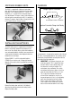
Installing the Telemetry Sensors in Your Vehicle SR3300T Receiver RPM/Speed Port RPM/Speed Sensor (Nitro) An infrared sensor is provided to record rpm values that can be converted by the transmitter unit to actual speed in mph or km/h. The sensor emits an infrared light and a receptor records the reflection vs. the absorption of light. It is necessary to place a reflective or light absorbing decal (provided) on the flywheel to allow the sensor to record rpm.
• Install the mount under the engine screw and adjust the sensor so it is 1/8” from the flywheel. Depending on your flywheel size, the sensor might have to be mounted in different orientations. RPM/Speed Sensor (Electric) In electric cars and trucks, the rpm sensor is mounted near the spur gear and gets rpm readings directly from that gear. A conversion in the transmitter can be programmed to give speed in mph or rpm. See the Telemetry Speed Unit section on rpm and speed for more details.
General Notes Temperature Sensor Installation (Nitro) • Install the loop as shown around the cylinder of the engine. It is best to place the sensor near the point at which the head meets the cylinder to get the most accurate consistent readings. Radio controlled models are a great source of pleasure. Unfortunately, they can also pose a potential hazard if not operated and maintained properly. It is imperative to install your radio control system correctly.
Tips on Using 2.4GHz Systems Your DSM equipped 2.4GHz system is intuitive to operate, functioning nearly identically to FM systems. Following are a few common questions from customers: 1. Q: Which do I turn on first, the transmitter or the receiver? A: It doesn’t matter, although it is suggested to turn the transmitter on first. If the receiver is turned on first, all channels will be driven to the failsafe position set during binding. When the transmitter is then turned on the transmitter scans the 2.
General Information Warranty Information FCC Information Warranty Period This device complies with part 15 of the FCC rules. Operation is subject to the following two conditions: (1) This device may not cause harmful interference, and (2) this device must accept any interference received, including interference that may cause undesired operation. Exclusive Warranty- Horizon Hobby, Inc.
Damage Limits Inspection or Repairs HORIZON SHALL NOT BE LIABLE FOR SPECIAL, INDIRECT OR CONSEQUENTIAL DAMAGES, LOSS OF PROFITS OR PRODUCTION OR COMMERCIAL LOSS IN ANY WAY CONNECTED WITH THE PRODUCT, WHETHER SUCH CLAIM IS BASED IN CONTRACT, WARRANTY, NEGLIGENCE, OR STRICT LIABILITY. Further, in no event shall the liability of Horizon exceed the individual price of the Product on which liability is asserted.
If you choose to pay by credit card, please include your credit card number and expiration date. Any repair left unpaid or unclaimed after 90 days will be considered abandoned and will be disposed of accordingly. Please note: non-warranty repair is only available on electronics and model engines.
® © 2008 Horizon Hobby, Inc. 4105 Fieldstone Road Champaign, Illinois 61822 (877) 504-0233 horizonhobby.