
Manual


2
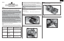
STEP 5
Unscrew and remove the Phillips head screw from the antenna baseplate and the
Phillips head screw from the antenna housing. Notice that of the 3 holes in the
base plate, the antenna routes through the rectangular hole.
STEP 6
Slide the antenna assembly out of the top of the transmitter.
STEP 7
Reassemble the new antenna assembly and the shaft. Route the coaxial wire
through the shaft until the wire exits the rectangular opening at the base of the
shaft. Align the shaft with the antenna housing until the Phillips head screw holes
line up. Be careful not to pinch the antenna wire when reinserting the shaft. Then
install the Phillips screw on the antenna housing.
STEP 8
Install the antenna assembly in the transmitter. Feed the antenna wire through
the rectangular opening in the metal baseplate. Make sure the key is in the non-
rectangular slot. Use care not to pinch the antenna wire. Fasten it in place using
the Phillips screw in the center hole.
STEP 9
Install the antenna connector on the RF module. Precise alignment is needed
so the two snap together. Carefully align the connector and press in place until
it clicks. Ensure proper connection by a slight “side-to-side” movement of the
antenna wire.
STEP 10
Confi rm the installation was done correctly by checking that all wires, screws
and other components are back to their original position with the new antenna
installed. Check to ensure no wires are kinked or will be pinched when the trans-
mitter is screwed back together. Reassemble the unit and perform a range check.
Range check procedures:
1. With the model resting on the ground, system powered and model secured,
stand 30 paces (approx. 90 feet) away from the model.
2. Face the model with the transmitter in your normal fl ying position and
depress and hold the bind button on the back of the transmitter. This causes
reduced power output from the transmitter.
3. You should have total control of the model with the button depressed at 30
paces (90 feet).
4. If control issues exist, contact the appropriate Horizon Service Center for
further assistance.
Note: If any time during or after the installation you do not feel confi dent about
the installation, please send it to the appropriate Horizon Service Center.
WARNING: ENSURE FUTURE ANTENNA SAFETY - Do not attempt to use the
antenna to bear any weight, pick up the transmitter by the antenna or alter
the antenna in any way. If the transmitter antenna or related components
become damaged the output strength can be severely impeded which will
likely lead to a crash, injury, and property damage.
©2010 Horizon Hobby, Inc., 4105 Fieldstone Road, Champaign, IL 61822 USA
Horizon Hobby Limited, Units 1-4 Ployters Rd, Staple Tye, Harlow, Essex, CM18 7NS, United Kingdom
Horizon Hobby GmbH, Hamburger Strasse 10, 25335 Elmshorn, Germany
The Spektrum trademark is used with permission of Bachmann Industries, Inc. Updated 1/13 27877.2
EN