SPMAR10360T AR10360T 10 Channel Telemetry Receiver User Guide AR10360T Telemetrieempfänger mit 10 Kanälen Bedienungsanleitung Guide de L’utilisateur - AR10360T Récepteur de télémétrie 10 Canaux Guidea Dell’utente - AR10360T Ricevitore di telemetria 10 CH
EN NOTICE All instructions, warranties and other collateral documents are subject to change at the sole discretion of Horizon Hobby, LLC. For up-to-date product literature, visit horizonhobby.com or towerhobbies.com and click on the support or resources tab for this product.
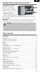
EN AR10360T AS3X and SAFE Telemetry Receiver The Spektrum™ AR10360T Receiver is full range with telemetry, and is compatible with all Spektrum™ DSM2® and DSMX® technology transmitters. Perform the setup for the AR10360T receiver through a compatible Spektrum Transmitter with Forward Programming. The Spektrum PC Programmer can be used for firmware updates. IMPORTANT: The AR10360T receiver only uses forward programming for the configuration, do not use the AS3X menu in the main transmitter menu.
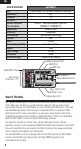
EN SPECIFICATIONS Type Application Channels Receivers Remote Receiver (not included) Modulation Telemetry Bind Method Failsafe Band Dimensions (LxWxH) Weight Input Voltage Resolution Antenna Length AR10360T DSM2/DSMX 10 CH AS3X Telemetry Receiver Air 10 1 SRXL2™ Remote Receiver Optional [SPM9747, SPM4651T] DSM2/DSMX Integrated Bind Button, Bind Plug Yes 2.4GHz 55 x 30 x 15mm 18g 3.
EN Telemetry The AR10360T features full range telemetry and will provide receiver battery voltage, flight log data, and variometer* and altitude* data without any additional sensors. Additional telemetry devices such as voltage sensors can be connected to the volt port, and XBus telemetry sensors can be connected through the XBus connector. Every XBus telemetry device has two XBus ports, and XBus telemetry sensors can be connected in a daisy chain in any order. See www.spektrumrc.
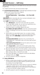
EN ANTENNA INSTALLATION The AR10360T receiver has coaxial style antennas. We recommend installing the antennas oriented 90º from each other and as far as possible from metal, batteries, carbon fiber or fuel tanks to maximize signal reception performance. Active portion of antenna NOTICE: Do not cut, kink, or modify the antennas. Damage to the coaxial portion of an antenna will reduce the performance of the antenna. Shortening or cutting off the 31mm tip will reduce the range.
EN Failsafe In the unlikely event the radio link is lost during use, the receiver will enable the selected failsafe mode. Smart Safe + Hold Last is the default failsafe mode on the AR10360T. Preset Failsafe and SAFE Failsafe modes are only available through Forward Programming. SmartSafe + Hold Last If loss of signal occurs, SmartSafe™ technology moves the throttle channel to the failsafe position (low throttle) set during binding. All other channels will hold their last position.
EN AR10360T Receiver — Basic AS3X Setup To use AS3X technology with the Spektrum AR10360T Receiver, the receiver needs to be set up with a compatible Spektrum transmitter. 1. Verify the basic setup and trim is accurate before attempting AS3X setup. 2. Forward Programming Setup: The receiver is directly configured through the Forward Programming menu. 1. Low throttle is required to enter Forward Programming, we recommend enabling throttle cut and verify it prevents motor operation.
EN AS3X Reaction Test This test ensures that the AS3X control system is functioning properly. 1. Assemble the aircraft, bind your transmitter to the receiver, and complete the AS3X First Time Setup in the Forward Programming menu before performing this test. 2. Raise the throttle above 25% to activate AS3X, then lower the throttle. Once the AS3X system is active, control surfaces move in respose to aircraft movement. AS3X remains active until the battery is disconnected.
EN AR10360T Receiver — SAFE Setup Setting up SAFE Technology on the AR10360T Receiver takes place in Forward Programming. 1. Complete the AS3X setup and verify operation in flight. 2. Forward Programming Setup: To add SAFE flight stabilization the Flight Modes on the receiver need to be configured. 1.
EN 3. If the airplane oscillates, immediately slow it down and reduce gain. Take note of which flight mode you are in and which axis the aircraft oscillates around. You can increase or decrease the base gain values of each axis separately for each flight mode within the Forward Programming menu after landing. 4. Tune gain values for each axis within each flight mode.
EN TIP: If you have not completed the First Time SAFE Setup, you will not see any SAFE related options on the F-Mode Setup Screens. 3. SAFE Flight Modes have an AS3X gain and a SAFE gain for pitch and roll axis. Both of these values are used for SAFE and may be tuned independently. 4. Enable the Panic function if you want to be able to trigger Panic (bailout) from that flight mode. This setting only defines if Panic is accessible from the selected Flight Mode.
EN Adding Flight Modes outside of Forward Programming (in the transmitter) Flight Modes outside of forward programming are set up in the main transmitter menu and are separate from Flight Modes set up within forward programming. Flight Modes in the transmitter tie together transmitter-based features like dual rates and expo, selected channels and positions, trim, and voice/sound features. 1. Select Model Setup -> Flight Mode Setup Assign a switch for the flight mode selection.
EN (AS3X) System Setup Select Forward Programming -> Gyro Settings -> System Settings -> • Relearn Servo Settings can be accessed if any changes are made to the model configuration outside of Forward Programming. If any changes are made to servo reversing, travel, sub-trim, wing type or tail type, you can execute this function instead of restoring factory defaults and redoing the entire setup. • Orientation can be changed from this menu if the receiver mounting is changed.
EN Other Settings (Forward Programming) System Setup Select Forward Programming -> Other Settings -> • Select Failsafe -> Select each channel and assign it to Preset or Hold Last. When you select a different channel for Output, a new group of settings appears. Capture Failsafe Positions -> Hold the control sticks in the desired failsafe positions and select Apply. Channel selections must be individually set in Forward Programming to apply the preset positions or each channel will default to Hold Last.
EN Differences between Self Leveling/Angle Demand and AS3X modes This section is generally accurate but does not take into account flight speed, battery charge status, and other limiting factors.
EN Flight Log Flight Log data can help you optimize the control link for your aircraft. Flight Log data is displayed on telemetry capable Spektrum transmitters. Using the Flight Log A - Fades on main receiver B - Fades on remote receiver L - Fades on remote receiver R - Not available on AR10360T F - Frame losses H - Holds Fades Represents the loss of one bit of information on one receiver. Fades are used to evaluate the performance of each individual receiver.
EN materials (e.g. turbine powered jets, scale aircraft with metalized finishes, aircraft with carbon fuselages, etc.), the following advanced range check will confirm that all receivers in the system are operating optimally as installed. This advanced range check allows the RF performance of each receiver to be evaluated independently. A telemetry-equipped Spektrum Transmitter is required for the advanced range test. 1. Stand approximately 100 feet away from the model. 2.
EN How QuickConnect™ Technology Works • When the receiver voltage drops below 3.5 volts, the system ceases to operate. • When power is restored, the receiver immediately attempts to reconnect. • If the transmitter was left on, the system reconnects typically in about 4/100 of a second. QuickConnect allows you to fly safely through most short duration power interruptions; however, to prevent a crash, correct the root cause of these interruptions before the next flight.
EN Oscillation- Sometimes called a wag, this is a back and forth movement similar to a vibration that may appear like a wobble. It may occur around any axis, roll, pitch or yaw. It is most likely to occur on one axis, not all three. Overshoot- When the stability system makes corrections it is a balancing act, if the response is too strong the system will go past where it should stop, this is called an overshoot.
EN Troubleshooting Guide AS3X Problem Possible Cause Damaged propeller or spinner Imbalanced propellereller Motor vibration Loose receiver Oscillation Loose aircraft controls Worn parts Irregular servo movement Gain too high Travel or Rates reduced causing reduced servo resolution Trim changes after initial setup Inconsistent flight performance Changes to SubTrim after initial setup Incorrect response to the AS3X Control Direction Test Aircraft was not kept immobile for 5 seconds after battery conne
EN Troubleshooting Guide Problem Aircraft will not respond to throttle but responds to other controls Possible Cause Solution Throttle not at idle and/or throttle trim too high Throttle servo travel is lower than 100% Reset controls with throttle stick and throttle trim at lowest setting Make sure throttle servo travel is 100% or greater (With battery disconnected from aircraft) Reverse throttle channel on transmitter Make sure motor is connected to the ESC Move powered transmitter a few feet from air
EN Troubleshooting Guide Problem Aircraft will not connect (after binding) to transmitter Possible Cause Solution Transmitter too near aircraft during connecting process Move powered transmitter a few feet from aircraft, disconnect and reconnect flight battery to aircraft Aircraft or transmitter is too close to large metal object, wireless source or another transmitter Move aircraft and transmitter to another location and attempt connecting again Bind plug left installed in bind port Aircraft bound
EN 1-Year Limited Warranty What this Warranty Covers—Horizon Hobby, LLC, (Horizon) warrants to the original purchaser that the product purchased (the “Product”) will be free from defects in materials and workmanship for a period of 1 year from the date of purchase.
EN visit our website at www.horizonhobby.com, submit a Product Support Inquiry, or call the toll free telephone number referenced in the Warranty and Service Contact Information section to speak with a Product Support representative.
EN Warranty and Service Contact Information Country of Purchase United States of America Horizon Hobby Contact Information Horizon Service Center (Repairs and Repair Requests) servicecenter.horizonhobby. com/RequestForm/ Horizon Product Support (Product Technical Assistance) Sales EU productsupport@ horizonhobby.com. 877-504-0233 Address 2904 Research Rd Champaign, Illinois, 61822 USA websales@horizonhobby.com 800-338-4639 Horizon Technischer Service service@horizonhobby.
EN IC Information CONTAINS IC: 6157A-SPMAR10360T CAN ICES-3 (B)/NMB-3(B) This device contains license-exempt transmitter(s)/receivers(s) that comply with Innovation, Science, and Economic Development Canada’s license-exempt RSS(s). Operation is subject to the following 2 conditions: This device may not cause interference. This device must accept any interference, including interference that may cause undesired operation of the device.
© 2021 Horizon Hobby, LLC. DSM, DSM2, DSMX, SAFE, AS3X, Spektrum Airware, SRXL2, SmartSafe, Hangar 9 and the Horizon Hobby logo are trademarks or registered trademarks of Horizon Hobby, LLC. The Spektrum trademark is used with permission of Bachmann Industries, Inc. All other trademarks, service marks and logos are property of their respective owners. US 7,391,320. US 9,056,667. US 9,753,457. US 9,930,567. US 10,078,329. US 10,419,970. US 10,849,013. Updated 09/21 59648.